. 2012 Jun 20;102(12):2697-705.
doi: 10.1016/j.bpj.2012.04.052. Epub 2012 Jun 19.

Cone outer segments: a biophysical model of membrane dynamics, shape retention, and lamella formation

Affiliations

Cone outer segments: a biophysical model of membrane dynamics, shape retention, and lamella formation

Joseph M Corless. Biophys J. .

Abstract

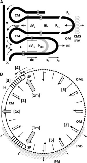
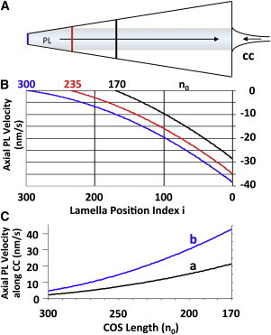
An hypothesis is developed to explain how the unique, right circular conical geometry of cone outer segments (COSs) in Xenopus laevis and other lower vertebrates is maintained during the cycle of axial shortening by apical phagocytosis and axial elongation via the addition of new basal lamellae. Extension of a new basal evagination (BE) applies radial (lateral) traction to membrane and cytoplasmic domains, achieving two coupled effects. 1), The bilayer domain is locally stretched/dilated, creating an entropic driving force that draws membrane components into the BE from the COS's distributed bilayer phase, i.e., plasmalemma and older lamellae (membrane recycling). Membrane proteins, e.g., opsins, are carried passively in this advective, bilayer-driven process. 2), With BE stretching, hydrostatic pressure within the BE cytoplasm is reduced slightly with respect to that of the axonemal cytoplasmic reservoir, allowing cytoplasmic flow into the BE. Attendant lowering of the reservoir's hydrostatic pressure facilitates the subsequent transfer of cytoplasm from lamellar domains to the reservoir (cytoplasmic recycling). The geometry of the BE reflects the membrane/cytoplasm ratio needed for its construction, and essentially specifies the ratio of components recycled from older lamellae. Length and taper angle of the COS reflect the ratio of recycled/new components constructing a new BE. The model also integrates the trajectories and dynamics of lamella open margin lattice components. Although not fully evaluated, the initial model has been assessed against the relevant literature, and three experimental predictions are derived.


Figures

Figure 1
Figure 1
Schematic views of a COS. (A) Overall COS geometry is rendered as a truncated right circular cone (frustum). The continuous membrane system has two main regions: a central stack of paired, parallel membrane units called lamellae, and a plasmalemma (PL) that partially encloses the lamellae along one side. The near side is cut into a longitudinal section (LS) to show internal relationships. The two membranes of each lamella are continuous along the open margin (OM) segment of the lamella perimeter; adjacent lamellae are continuous via closed margin (CM) or rim segments (Figs.1C). All four membrane domains are continuous at saddle points (SPs) (Figs. S2 and S3). The COS is continuous with the cone inner segment (CIS) via the connecting cilium (CC). Near the CC base, the CIS PL forms a series of ridges and grooves: the periciliary ridge complex (PRC) (3). From the CIS perimeter, calycal processes (CPs) project apically along the COS surface. A short stretch of OM lattice (OML) is indicated, extending past SPs to the PL surface. Axial elements of the OML connect adjacent lamellae; radial elements connect OMs to CPs (4,5). Developing lamellae (BE = basal evaginations) expand laterally in the space between COS and CIS (enlarged for visibility). Within the COS, paired membrane folds of smaller size (partial discs = PD) are also present. Drawing by Dr. Bradley R. Smith (adapted from (6) with permission from Elsevier). (B) Cross section through the COS. One lamella surface (Lam) is shown with OM and CM segments. These segments are continuous with the PL at SPs (Fig. S2 and Fig. S3). The cytoplasmic reservoir consists of axonemal cytoplasm (CA; ciliary matrix with microtubules) and flanking cytoplasmic sheaths (CS) of approximate constant width. The PL is similarly parsed: axonemal plasmalemma (PA) and plasmalemmal sheaths (PS). Electron micrographs ((4); their Fig. 3) show linear densities (L) spanning the CS, linking PS and CM surfaces near SPs. Line LS approximates the section planes in A and C. (C) Longitudinal section through the COS near LS, showing the changing lamella perimeter organization near an SP. CS width is ∼6.7 nm ((4); their Fig. 3A and B). Within the left CS, lines (L) depict PS-to-CM densities (4). On the right, similar lines suggest how CMs might be linked to OML elements transferred to the PS near SPs. Occasionally, cytoplasmic densities (CD) span the lamellar cytoplasm (CL) near CM and OM segments. Lamella cytoplasm is continuous with the cytoplasmic reservoir via the CM gap.
Figure 2
Figure 2
(A) Axial section through a COS with 10 lamellae of axial spacing d = 34.6 nm (not to scale), basal radius r0 = 2.1 μm, and taper angle α = 9.5°. (B) The same COS after addition of one new BL in the model. Each preformed lamella is advanced apically by distance d. Axial positions i = [0,10] for both sets of lamellae are indicated at the right. The oblique arrow indicates lamella 4 advancing to position 5. The most basal, full-sized lamella (basal lamella; BL) is always indexed to position 0. The z coordinate of each lamella i is zi = i × d.
Figure 3
Figure 3
Proposed distribution of lamella forces. (A) Differential forces and flows associated with the BL and the BE are discussed in the text. During recycling, the ratio of membrane/cytoplasmic volume lost from each lamella basically reflects the ratio demanded by the growing BE. Hydrostatic pressures: PE extracellular; PCL lamellar cytoplasm; PCR cytoplasmic reservoir; PCBE BE cytoplasm. Intracellular arrows: cytoplasmic recycling pattern. Scale: opsins (R): 75 Å long in the z direction (40). (B) Cross-sectional representation of structural changes and component flows in a lamella. The event sequence [1] → [4] is discussed in text. The outwardly directed arrows [5] represent a radial component of the small pressure increase postulated within lamella cytoplasm. Dynamic linkages between the COS surface and surrounding CMS and interphotoreceptor matrix might also oppose reduction in lamella radius and contribute to maintaining circular lamella shape. CM = closed margin; OM = open margin; OML = OM lattice; SP = saddle point. Spanning cytoplasmic sheaths near SPs, short links join the CM to PSs.
Figure 4
Figure 4
(A) Predicted basal flow of lamella-derived membrane components along the COS PL. New components arrive via the CC. (B) PL velocity gradient versus number of lamellae (n0 = 170, 235, and 300). (C) PL velocity of membrane components near the base of the CC versus n0. Curve a is computed using the entire circumference of the CC near its base (diameter ≈ 35 nm (3)). Because Y connectors within the CC involve about one-half of its PL, curve b reflects this reduced membrane flow area.
Figure 5
Figure 5
Predicted basal lamella composition due to advective flows only (no diffusion corrections (6)): flow rates and fractional contributions from NEW (via CC) and OLDER (recycled) components versus COS length. The composition ordinate applies to both membrane area and cytoplasmic volume.
Figure 6
Figure 6
Predicted trajectories of open margin particles (dots and arrowheads on trajectories j = ±100 indicate directions of movement). (A) Z-axis projection. This COS has n0 = 300 lamellae. Basal (i = 0) and apical perimeters (i = 300; tip) are labeled. The SP line separates PL and OM surfaces. Trajectories (blue) are plotted for a subset of OM particles: j = ± 4,25,50,75,…,250,265. CPs = 0–9 are shown on one side at 20° intervals. Each CP projects from COS base to tip. Most OM particles will interact with several CPs. (B) Lateral view with +j OM particle trajectories shown in orthographic projection. PL contour lines indicate axial intervals of 30 lamellae. Five CPs are included: +[2–6]. Z-axis scale: z′ = 0.785 × z.

Similar articles

Cited by

References

    1. Moody M.F., Robertson J.D. The fine structure of some retinal photoreceptors. J. Biophys. Biochem. Cytol. 1960;7:87–92. - PMC - PubMed
    1. Nilsson S.E.G. The ultrastructure of the receptor outer segments in the retina of the leopard frog (Rana pipiens) J. Ultrastruct. Res. 1965;12:207–231. - PubMed
    1. Peters K.-R., Palade G.E., Papermaster D.S. Fine structure of a periciliary ridge complex of frog retinal rod cells revealed by ultrahigh resolution scanning electron microscopy. J. Cell Biol. 1983;96:265–276. - PMC - PubMed
    1. Fetter R.D., Corless J.M. Morphological components associated with frog cone outer segment disc margins. Invest. Ophthalmol. Vis. Sci. 1987;28:646–657. - PubMed
    1. Corless J.M., Worniałło E., Fetter R.D. Modulation of disk margin structure during renewal of cone outer segments in the vertebrate retina. J. Comp. Neurol. 1989;287:531–544. - PubMed

Publication types

MeSH terms

LinkOut - more resources