

doi: 10.1364/OL.37.002247.
Optical magnetometer array for fetal magnetocardiography
Affiliations
- PMID: 22739870
- PMCID: PMC3386557
- DOI: 10.1364/OL.37.002247
Item in Clipboard
Optical magnetometer array for fetal magnetocardiography
Opt Lett.
.
Abstract
We describe an array of spin-exchange-relaxation-free optical magnetometers designed for detection of fetal magnetocardiography (fMCG). The individual magnetometers are configured with a small volume with intense optical pumping, surrounded by a large pump-free region. Spin-polarized atoms that diffuse out of the optical pumping region precess in the ambient magnetic field and are detected by a probe laser. Four such magnetometers, at the corners of a 7 cm square, are configured for gradiometry by feeding back the output of one magnetometer to a field coil to null uniform magnetic field noise at frequencies up to 200 Hz. We present the first measurements of fMCG signals using an atomic magnetometer.
Figures
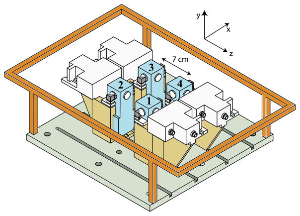
(Color online) Biomagnetometer array. Four magnetometers are symmetrically located in the plane of a field coil. The output P1x of one magnetometer is fed back to actively null B1y. Each channel consists of a heated glass cell (numbered)
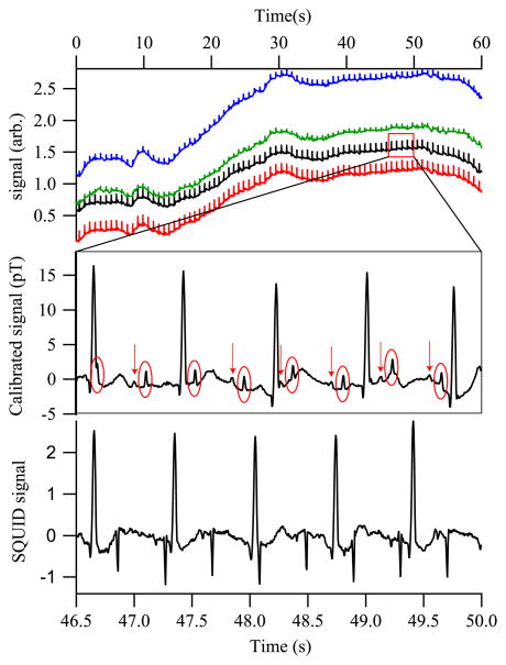
(Color online) (Top) Real-time MCG from a 31 week fetus, showing all magnetometer channels. (Middle) Portion of channel 2, with an 80 Hz low-pass filter and a 60 Hz comb filter applied. The fetal QRS complexes are circled; arrows identify the fetal P-wave components. (Bottom) SQUID gradiometer signal with the same filters applied. The gradiometry suppresses the maternal MCG as compared to the fMCG.
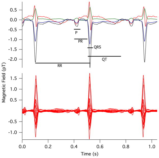
(Color online) Comparison of the (top) prototype optical magnetometer and (bottom) commercial SQUID signals, with timings between features corresponding to Table 1.
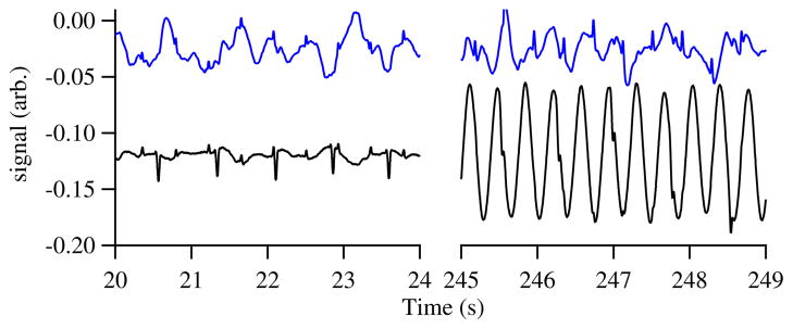
(Color online) Two feedback scenarios. The lower trace is the current supplied to the large field coil to hold the signal constant at channel 4. The upper trace shows the field at another channel. (left) Data with a nearby ventilation fan off; the maternal signal is nearly the same size at the two channels, so it is largely absent from the upper channel. (right) With the fan on, the fMCG is still visible in the upper channel thanks to the feedback compensation.
References
-
- Kominis IK, Kornack TW, Allred JC, Romalis MV. Nature. 2003;422:596. - PubMed
-
- Happer W, Tam AC. Phys Rev A. 1977;16:1877.
-
- Xia H, Baranga ABA, Hoffman D, Romalis MV. Appl Phys Lett. 2006;89:211104.
-
- Johnson CN, Schwindt P, Weisend M. Appl Phys Lett. 2010;97:243703.
-
- Knappe S, Sander TH, Kosch O, Wiekhorst F, Kitching J, Trahms L. Appl Phys Lett. 2010;97:133703.
Publication types
MeSH terms
Grants and funding
LinkOut - more resources
Full Text Sources
Other Literature Sources
