. 2012 Sep;11(9):768-74.
doi: 10.1038/nmat3357. Epub 2012 Jul 1.

Rapid casting of patterned vascular networks for perfusable engineered three-dimensional tissues

Affiliations

Rapid casting of patterned vascular networks for perfusable engineered three-dimensional tissues

Jordan S Miller et al. Nat Mater. 2012 Sep.

Abstract

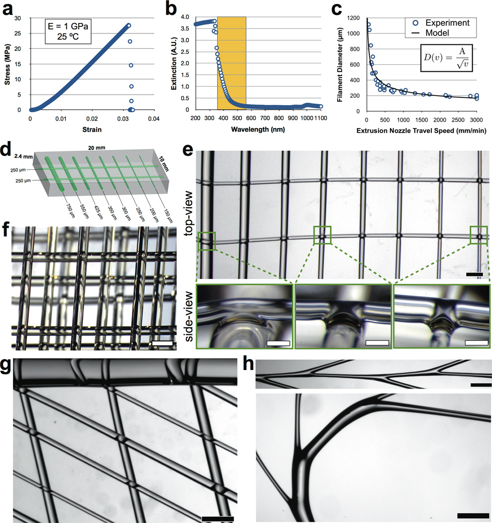
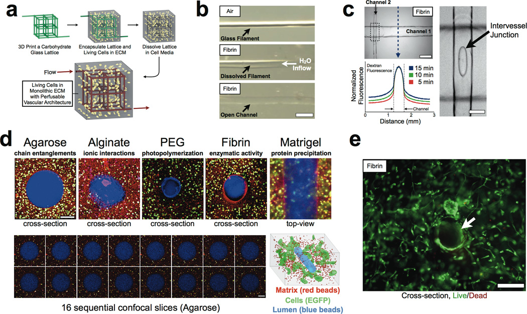
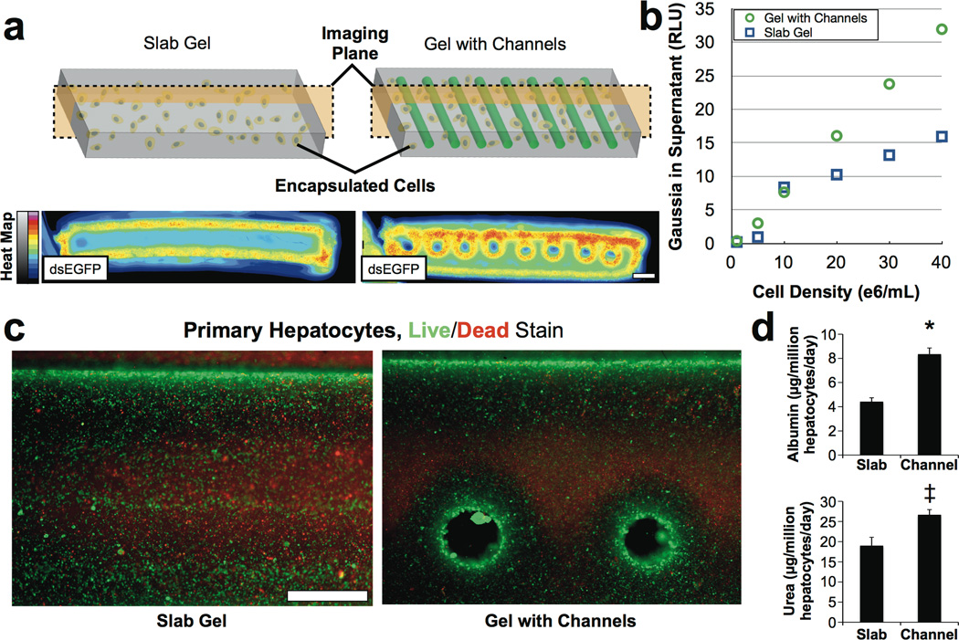
In the absence of perfusable vascular networks, three-dimensional (3D) engineered tissues densely populated with cells quickly develop a necrotic core. Yet the lack of a general approach to rapidly construct such networks remains a major challenge for 3D tissue culture. Here, we printed rigid 3D filament networks of carbohydrate glass, and used them as a cytocompatible sacrificial template in engineered tissues containing living cells to generate cylindrical networks that could be lined with endothelial cells and perfused with blood under high-pressure pulsatile flow. Because this simple vascular casting approach allows independent control of network geometry, endothelialization and extravascular tissue, it is compatible with a wide variety of cell types, synthetic and natural extracellular matrices, and crosslinking strategies. We also demonstrated that the perfused vascular channels sustained the metabolic function of primary rat hepatocytes in engineered tissue constructs that otherwise exhibited suppressed function in their core.


Figures

Figure 1
Figure 1
Carbohydrate glass material properties and filament architecture formation. (a) Stress-strain curve from uniaxial compression testing indicates the carbohydrate glass is a stiff and brittle material at 25 °C, with Young’s modulus = 1 GPa (measured in the linear regime), maximum strength of 28 MPa, maximum strain of 3.25%. (b) Optical extinction for a 1 cm sample of carbohydrate glass indicates the material transmits light wavelengths commonly used during biocompatible imaging and photopolymerization (365–550 nm, shaded box). (c) During thermal extrusion and 3D printing, filament diameter is controlled by the travel speed of the extrusion nozzle and follows a simple power law from glass fiber drawing (equation inset). (d) Architectural design of a multiscale carbohydrate glass lattice (green). (e) Top view of the multiscale architectural design in (d) 3D printed in carbohydrate glass (scale bar = 1 mm). Interfilament melt fusions are magnified and shown in side-view (scale bars = 200 µm). (f) Multilayered lattices are fabricated in minutes with precise lateral and axial positioning resolution (scale bar = 1 mm). (g) A multiscale architecture showing a single 1 mm filament (top) connected to angled arrays of smaller interconnected filaments (scale bar = 1 mm). (h) Serial y-junctions and curved filaments can also be fabricated (scale bars = 1 mm).
Figure 2
Figure 2
Monolithic tissue construct containing patterned vascular architectures and living cells. (a) Schematic overview. An open, interconnected, self-supporting carbohydrate glass lattice is 3D printed to serve as the sacrificial element for the casting of vascular architectures. The lattice is encapsulated in ECM along with living cells. The lattice is dissolved in minutes in cell media without damage to nearby cells. The process yields a monolithic tissue construct with a vascular architecture that matches the original lattice. (b) A single carbohydrate glass fiber (200 µm in diameter, top) is encapsulated in a fibrin gel. Following ECM crosslinking, the gel and filament are immersed in aqueous solution and the dissolved carbohydrates are flowed out of the resulting channel (middle). Removal of the filament yields an open perfusable channel in the fibrin gel (bottom, scale bar = 500 µm). See Supplementary Movie 1 for full time course. (c) A fibrin gel with patterned interconnected channels of different diameters supports convective and diffusive transport of a fluorescent dextran injected into the channel network (upper left, phase contrast, scale bar = 500 µm). Line plot of normalized fluorescence across the gel and channel (blue arrow) shows a sinusoidal profile in the channel (between dotted black lines) characteristic of a cylinder and temporal diffusion from the channel into the bulk gel. Enlargement of the dotted box region shows an oval intervessel junction between the two perpendicular channels (right, scale bar = 100 µm). (d) Cells constitutively expressing EGFP were encapsulated (5e6/mL) in a variety of ECM materials then imaged with confocal microscopy to visualize the matrix (red beads), cells (10T1/2, green) and the perfusable vascular lumen (blue beads) shown schematically (bottom right). The materials have varied crosslinking mechanisms (annotated above images) but were all able to be patterned with vascular channels. Scale bars = 200 µm. (e) Representative cross-section image of unlabeled HUVEC (1e6/mL) and 10T1/2 (1e6/mL) co-cultures (not expressing EGFP) encapsulated uniformly in the interstitial space of fibrin gel (10 mg/mL) with perfusable networks after two days in culture were stained with a fluorescent Live/Dead assay (green, Calcein AM; red, Ethidium Homodimer). Cells survive and spread near open cylindrical channels (highlighted with white arrow). Scale bar = 200 µm.
Figure 3
Figure 3
Demonstrated control over the three key compartments of vascularized solid tissues, shown schematically in (a) as the “vascular unit cell” comprised of the vascular lumen, endothelial cells lining the vascular wall, and the interstitial zone containing matrix and encapsulated cells. (b) Patterned vascular channels support positive pressure and pulsatile flow of human blood with intervessel junctions supporting branched fluid flow (left). Spiral flow patterns (right, 0.4 sec) are characteristic of non-laminar flow through cylindrical channels. See Supplementary Movies 2 and 3, Scale bars = 1 mm, left; 2 mm, right. (c) Control of the interstitial zone and the lining endothelium of vascularized tissue constructs is demonstrated by encapsulating 10T1/2 cells (1.5e6/mL, constitutively expressing EGFP) in the interstitial space of a fibrin gel (10 mg/mL) followed by seeding of HUVECs (constitutively expressing mCherry) throughout the vascular network via a single lumenal injection (see Methods). After one day in culture a confocal z-stack montage demonstrated HUVECs residing in the vascular space with 10T1/2 uniformly distributed throughout the bulk gel. Scale bar = 1 mm. (d) A partial z-stack of two intersecting channels demonstrated endothelialization of channel walls and across the intervessel junction, while in the surrounding bulk gel 10T1/2 cells are seen beginning to spread out in 3D. See Supplementary Movie 4 for the complete 700 µm z-stack from (d). (e) After 9-days in culture, cross-section imaging of a representative channel (optical thickness and z-position = 10 µm) demonstrated that the endothelial monolayer lining the vascular lumen became surrounded by 10T1/2 cells. Scale bar = 200 µm. (f) Endothelial cells formed single and multicellular sprouts (arrowheads) from patterned vasculature as seen in a z-stack (optical thickness = 200 µm) from deeper within the gel (z-position = 300 µm, left). Even deeper imaging (z-position = 950 µm, optical thickness = 100 µm, right) confirmed that the vascular lumen remained open throughout vessels and intervessel junctions and that endothelial cells also sprouted from larger vessels (arrowheads). See Supplementary Movie 5 for the complete 1 mm z-stack from (e,f).
Figure 4
Figure 4
Perfusion channels sustain cellular metabolic function in the core of thick, densely populated tissue constructs. (a) Representative cross-section image montages of PEG hydrogels containing 40e6 HEK cells/mL after three days in culture. The intracellular dsEGFP reporter spatially indicates cells are active at the gel slab perimeter and circumferentially around perfusion channels, but not elsewhere in the gel core. Scale bar = 2 mm. (b) A functional enzyme assay of secreted Gaussia luciferase from these constructs indicates that the channel architecture preserves cell function even at high cell densities, where function in slab gels quickly falls off. (c) Primary rat hepatocytes (24e6 hepatocytes/mL) and stabilizing stromal fibroblasts in agarose gels (slab vs. channeled) after 8 days of culture were stained with a fluorescent Live/Dead assay (green, Calcein AM; red, Ethidium Homodimer). Cells survive at the gel perimeter and near perfused channels, and survival decayed deeper in the gels. Scale bar = 1 mm. (d) Assessment of albumin secretion (top) and urea synthesis (bottom) by primary hepatocytes (16e6/mL) in gels after 8 days of culture demonstrated improved hepatic function in channeled gels compared to slab gels. Error bars represent standard error, p-values for channel versus slab gel comparisons: * < 0.0051; ‡ < 0.045.

Comment in

References

    1. Radisic M, Yang L, Boublik J, Cohen RJ, Langer R, Freed LE, Vunjak-Novakovic G. Medium perfusion enables engineering of compact and contractile cardiac tissue. Am J Physiol Heart Circ Physiol. 2004;286:H507–H516. - PubMed
    1. Langer R, Vacanti JP. Tissue engineering. Science. 1993;260:920–926. - PubMed
    1. Griffith LG, Swartz MA. Capturing complex 3d tissue physiology in vitro. Nat Rev Mol Cell Biol. 2006;7:211–224. - PubMed
    1. Vunjak-Novakovic G, Scadden DT. Biomimetic platforms for human stem cell research. Cell Stem Cell. 2011;8:252–261. - PMC - PubMed
    1. Schmidt-Nielsen K. Scaling in biology: the consequences of size. J Exp Zool. 1975;194:287–307. - PubMed

Publication types

MeSH terms