

Localization of dense intracranial electrode arrays using magnetic resonance imaging
- PMID: 22759995
- PMCID: PMC4408869
- DOI: 10.1016/j.neuroimage.2012.06.039
Localization of dense intracranial electrode arrays using magnetic resonance imaging
Abstract
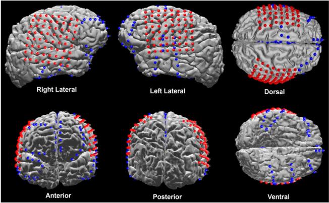
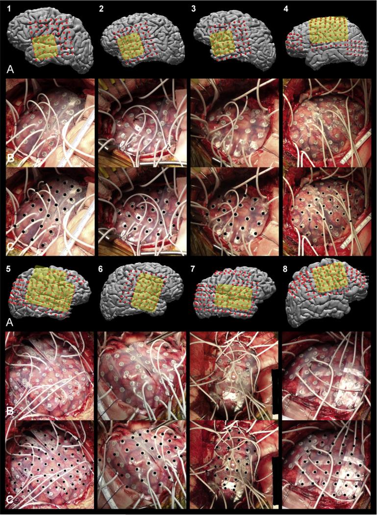
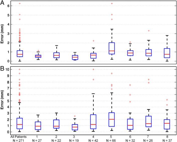
Intracranial electrode arrays are routinely used in the pre-surgical evaluation of patients with medically refractory epilepsy, and recordings from these electrodes have been increasingly employed in human cognitive neurophysiology due to their high spatial and temporal resolution. For both researchers and clinicians, it is critical to localize electrode positions relative to the subject-specific neuroanatomy. In many centers, a post-implantation MRI is utilized for electrode detection because of its higher sensitivity for surgical complications and the absence of radiation. However, magnetic susceptibility artifacts surrounding each electrode prohibit unambiguous detection of individual electrodes, especially those that are embedded within dense grid arrays. Here, we present an efficient method to accurately localize intracranial electrode arrays based on pre- and post-implantation MR images that incorporates array geometry and the individual's cortical surface. Electrodes are directly visualized relative to the underlying gyral anatomy of the reconstructed cortical surface of individual patients. Validation of this approach shows high spatial accuracy of the localized electrode positions (mean of 0.96 mm ± 0.81 mm for 271 electrodes across 8 patients). Minimal user input, short processing time, and utilization of radiation-free imaging are strong incentives to incorporate quantitatively accurate localization of intracranial electrode arrays with MRI for research and clinical purposes. Co-registration to a standard brain atlas further allows inter-subject comparisons and relation of intracranial EEG findings to the larger body of neuroimaging literature.
Copyright © 2012 Elsevier Inc. All rights reserved.
Figures


Similar articles
-
Recording human electrocorticographic (ECoG) signals for neuroscientific research and real-time functional cortical mapping.J Vis Exp. 2012 Jun 26;(64):3993. doi: 10.3791/3993. J Vis Exp. 2012. PMID: 22782131 Free PMC article.
-
Recursive grid partitioning on a cortical surface model: an optimized technique for the localization of implanted subdural electrodes.J Neurosurg. 2013 May;118(5):1086-97. doi: 10.3171/2013.2.JNS121450. Epub 2013 Mar 15. J Neurosurg. 2013. PMID: 23495883
-
Simultaneous intracranial EEG-fMRI in humans: protocol considerations and data quality.Neuroimage. 2012 Oct 15;63(1):301-9. doi: 10.1016/j.neuroimage.2012.05.056. Epub 2012 May 29. Neuroimage. 2012. PMID: 22652020
-
Automated electrocorticographic electrode localization on individually rendered brain surfaces.J Neurosci Methods. 2010 Jan 15;185(2):293-8. doi: 10.1016/j.jneumeth.2009.10.005. Epub 2009 Oct 27. J Neurosci Methods. 2010. PMID: 19836416
-
Brain functional localization: a survey of image registration techniques.IEEE Trans Med Imaging. 2007 Apr;26(4):427-51. doi: 10.1109/TMI.2007.892508. IEEE Trans Med Imaging. 2007. PMID: 17427731 Review.
Cited by
-
Binding of cortical functional modules by synchronous high-frequency oscillations.Nat Hum Behav. 2024 Oct;8(10):1988-2002. doi: 10.1038/s41562-024-01952-2. Epub 2024 Aug 12. Nat Hum Behav. 2024. PMID: 39134741
-
Interictal epileptiform discharges shape large-scale intercortical communication.Brain. 2019 Nov 1;142(11):3502-3513. doi: 10.1093/brain/awz269. Brain. 2019. PMID: 31501850 Free PMC article.
-
Shared computational principles for language processing in humans and deep language models.Nat Neurosci. 2022 Mar;25(3):369-380. doi: 10.1038/s41593-022-01026-4. Epub 2022 Mar 7. Nat Neurosci. 2022. PMID: 35260860 Free PMC article.
-
Speech-induced suppression and vocal feedback sensitivity in human cortex.bioRxiv [Preprint]. 2024 Jun 21:2023.12.08.570736. doi: 10.1101/2023.12.08.570736. bioRxiv. 2024. Update in: Elife. 2024 Sep 10;13:RP94198. doi: 10.7554/eLife.94198. PMID: 38370843 Free PMC article. Updated. Preprint.
-
Forced conceptual thought induced by electrical stimulation of the left prefrontal gyrus involves widespread neural networks.Epilepsy Behav. 2020 Mar;104(Pt A):106644. doi: 10.1016/j.yebeh.2019.106644. Epub 2020 Jan 14. Epilepsy Behav. 2020. PMID: 31951969 Free PMC article.
References
-
- Ashburner J. A fast diffeomorphic image registration algorithm. Neuroimage. 2007;38:95–113. - PubMed
-
- Behrens E, Zentner J, van Roost D, Hufnagel A, Elger CE, Schramm J. Subdural and depth electrodes in the presurgical evaluation of epilepsy. Acta Neurochir. 1994;128:84–87. - PubMed
-
- Bootsveld K, Träber F, Kaiser WA, Layer G, Elger CE, Hufnagel A, Gieseke J, Reiser M. Localisation of intracranial EEG electrodes using three dimensional surface reconstructions of the brain. Eur. Radiol. 1994;4:52–56. - PubMed
-
- Bronstein AM, Bronstein MM, Kimmel R. Numerical geometry of non-rigid shapes. 1st ed. Springer; 2010.
Publication types
MeSH terms
Grants and funding
LinkOut - more resources
Full Text Sources
Other Literature Sources
Medical