

Room temperature operable autonomously moving bio-microrobot powered by insect dorsal vessel tissue
- PMID: 22808004
- PMCID: PMC3394766
- DOI: 10.1371/journal.pone.0038274
Room temperature operable autonomously moving bio-microrobot powered by insect dorsal vessel tissue
Abstract
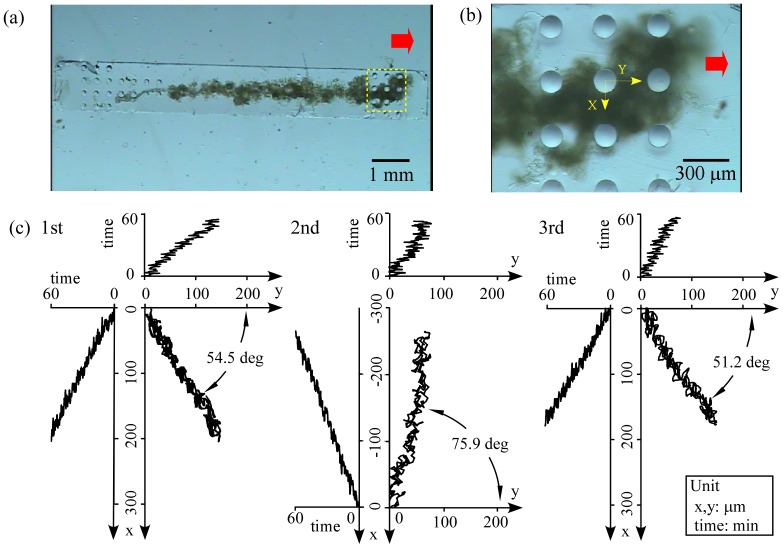
Living muscle tissues and cells have been attracting attention as potential actuator candidates. In particular, insect dorsal vessel tissue (DVT) seems to be well suited for a bio-actuator since it is capable of contracting autonomously and the tissue itself and its cells are more environmentally robust under culturing conditions compared with mammalian tissues and cells. Here we demonstrate an autonomously moving polypod microrobot (PMR) powered by DVT excised from an inchworm. We fabricated a prototype of the PMR by assembling a whole DVT onto an inverted two-row micropillar array. The prototype moved autonomously at a velocity of 3.5 × 10(-2) µm/s, and the contracting force of the whole DVT was calculated as 20 µN. Based on the results obtained by the prototype, we then designed and fabricated an actual PMR. We were able to increase the velocity significantly for the actual PMR which could move autonomously at a velocity of 3.5 µm/s. These results indicate that insect DVT has sufficient potential as the driving force for a bio-microrobot that can be utilized in microspaces.
Conflict of interest statement
Figures
Similar articles
-
Rapidly-moving insect muscle-powered microrobot and its chemical acceleration.Biomed Microdevices. 2012 Dec;14(6):979-86. doi: 10.1007/s10544-012-9700-5. Biomed Microdevices. 2012. PMID: 22945325
-
Long-term and room temperature operable bioactuator powered by insect dorsal vessel tissue.Lab Chip. 2009 Jan 7;9(1):140-4. doi: 10.1039/b809299k. Epub 2008 Oct 21. Lab Chip. 2009. PMID: 19209346
-
Culture of insect cells contracting spontaneously; research moving toward an environmentally robust hybrid robotic system.J Biotechnol. 2008 Jan 20;133(2):261-6. doi: 10.1016/j.jbiotec.2007.08.042. Epub 2007 Aug 31. J Biotechnol. 2008. PMID: 17997182
-
Bio-hybrid muscle cell-based actuators.Biomed Microdevices. 2012 Dec;14(6):987-98. doi: 10.1007/s10544-012-9697-9. Biomed Microdevices. 2012. PMID: 22960907 Review.
-
Towards compliant and wearable robotic orthoses: A review of current and emerging actuator technologies.Med Eng Phys. 2016 Apr;38(4):317-25. doi: 10.1016/j.medengphy.2016.01.010. Epub 2016 Feb 26. Med Eng Phys. 2016. PMID: 26923385 Review.
Cited by
-
Wirelessly Powered 3D Printed Hierarchical Biohybrid Robots with Multiscale Mechanical Properties.Adv Funct Mater. 2022 Aug 1;32(31):2202674. doi: 10.1002/adfm.202202674. Epub 2022 May 3. Adv Funct Mater. 2022. PMID: 36313126 Free PMC article.
-
Rise of cyborg microrobot: different story for different configuration.IET Nanobiotechnol. 2019 Sep;13(7):651-664. doi: 10.1049/iet-nbt.2018.5374. IET Nanobiotechnol. 2019. PMID: 31573533 Free PMC article. Review.
-
Construction of intelligent moving micro/nanomotors and their applications in biosensing and disease treatment.Theranostics. 2023 May 15;13(9):2993-3020. doi: 10.7150/thno.81845. eCollection 2023. Theranostics. 2023. PMID: 37284438 Free PMC article. Review.
-
3D-printed microrobots from design to translation.Nat Commun. 2022 Oct 5;13(1):5875. doi: 10.1038/s41467-022-33409-3. Nat Commun. 2022. PMID: 36198675 Free PMC article. Review.
-
Cardiac Muscle Cell-based Actuator and Self-stabilizing Biorobot - Part 2.J Vis Exp. 2017 May 9;(123):55643. doi: 10.3791/55643. J Vis Exp. 2017. PMID: 28518129 Free PMC article.
References
-
- Ilievski F, Mazzeo AD, Shepherd RF, Chen X, Whitesides GM. Soft robotics for chemists. Angew Chem Int Ed. 2011;50:1890–1895. - PubMed
-
- Madden JD. Mobile robots: motor challenges and materials solutions. Science. 2007;318:1094–1097. - PubMed
-
- Hunter W, Lafontaine S. A comparison of muscle with artificial actuators. Technical Digest. IEEE Solid-State Sensor and Actuator Workshop. 1992:178–185.
-
- Morishima K, Tanaka Y, Ebara M, Shimizu T, Kikuchi A, et al. Demonstration of a bio-microactuator powered by cultured cardiomyocytes coupled to hydrogel micropillars. Sens Act B. 2006;119:345–350.
-
- Tanaka Y, Morishima K, Shimizu T, Kikuchi A, Yamato M, et al. Demonstration of a PDMS-based bio-microactuator using cultured cardiomyocytes to drive polymer micropillars. Lab Chip. 2006;6:230–235. - PubMed
Publication types
MeSH terms
LinkOut - more resources
Full Text Sources
