. 2012;7(7):e40887.
doi: 10.1371/journal.pone.0040887. Epub 2012 Jul 19.

Generalization of the dynamic clamp concept in neurophysiology and behavior

Affiliations

Generalization of the dynamic clamp concept in neurophysiology and behavior

Pablo Chamorro et al. PLoS One. 2012.

Abstract

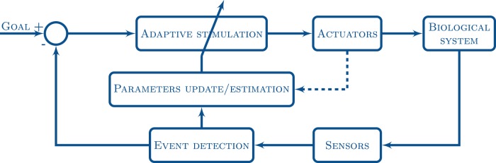
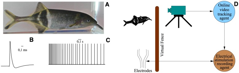
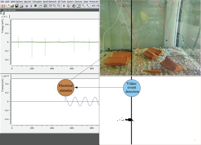
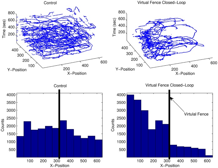
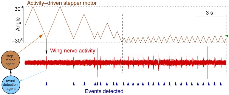
The idea of closed-loop interaction in in vitro and in vivo electrophysiology has been successfully implemented in the dynamic clamp concept strongly impacting the research of membrane and synaptic properties of neurons. In this paper we show that this concept can be easily generalized to build other kinds of closed-loop protocols beyond (or in addition to) electrical stimulation and recording in neurophysiology and behavioral studies for neuroethology. In particular, we illustrate three different examples of goal-driven real-time closed-loop interactions with drug microinjectors, mechanical devices and video event driven stimulation. Modern activity-dependent stimulation protocols can be used to reveal dynamics (otherwise hidden under traditional stimulation techniques), achieve control of natural and pathological states, induce learning, bridge between disparate levels of analysis and for a further automation of experiments. We argue that closed-loop interaction calls for novel real time analysis, prediction and control tools and a new perspective for designing stimulus-response experiments, which can have a large impact in neuroscience research.


Conflict of interest statement

Competing Interests: The authors have declared that no competing interests exist.

Figures

Figure 1
Figure 1. Schematic representation of the goal-driven closed-loop for the activity-dependent stimulation used in the three examples discussed in this paper.
The activity of the biological system is monitored through a set of sensors (e.g. microelectrodes, cameras). A given goal drives the detection of specific events that are used to control the adaptive stimulation (through specific actuators) that will lead to this goal. Simultaneously, the output of the event detection and the stimulation can be used for identification purposes by updating or estimating the parameters that control this loop. Examples of goals for the closed-loop interaction are to exert control, reveal or characterize the dynamics, or to achieve the automation of a experiment as we illustrate in the next sections.
Figure 2
Figure 2. Transient effect of GABA microinjections on cardiac cells in a traditional open-loop protocol with periodic stimulation.
The top panel shows the effect of GABA on the membrane potential of a CPG neuron from the cardiac ganglion of Carcinus maenas. The vertical arrow indicates the instant in which a burst of periodic GABA microinjections (vertical lines) of 50 ms of duration and separated by 200 ms takes place. These injections produce a transient inhibitory effect on the bursting activity. The bottom panel is a blow up of the squared region on the top panel. Single pulses evoke a much more transient response as shown in Fig. 4, which is used to control the number of spikes in each burst during the closed-loop experiment.
Figure 3
Figure 3. Activity-dependent drug microinjection.
Panel A shows a schematic representation of the closed-loop drug stimulation protocol. In this example, the membrane potential of a neuron is monitored by an event detection algorithm to perform the activity-dependent drug microinjection. When an event is detected, the software sends a signal to the microinjector and the neurotransmitter or neuromodulator is released. Panel B shows the real time (RT) stimulation protocol we employed in the experiments discussed in this section. This adaptive protocol consists of a double 1 mM GABA injection (two 40 ms pulses separated by 30 ms) when the third spike is detected at the beginning of a burst of a cardiac neuron (vertical lines indicate the detection of single spikes, arrows indicate the instant in which the microinjection takes place). The resulting inhibitory closed-loop is used to achieve a desired number of spikes in the bursting activity of these neurons.
Figure 4
Figure 4. Results of the activity-dependent drug stimulation protocol.
The rows on the first column show the membrane potential time series during control (top row), stimulation (middle row) and recovery after washout (bottom row). The rows on the second column show the raster plots for control (top), stimulation (middle) and recovery (bottom). The rows on the third column show the distribution of the number of spikes in each burst for the three time series. Finally, the panels on the fourth column show the inter-spike intervals (ISI) return maps during control (top), stimulation (middle) and recovery (bottom). Note that during the stimulation, the number of spikes per burst drastically decreased because of the RT activity-dependent GABA microinjections.
Figure 5
Figure 5. Closed-loop video-event driven stimulation.
A: Electric fish Gnathonemus petersii. B: Single electrical organ discharge of this fish. C: a typical train of activity (signals are squared in this plot). D: Schematic representation of the closed-loop video-event driven stimulation.
Figure 6
Figure 6. Virtual water fence through position-dependent stimulation.
When the fish crosses a virtual barrier (vertical black line on the right panels) an aversive stimulus is delivered (bottom left) so that the fish stays in a specific space of the water tank. The top left panel shows the electrical activity of the fish.
Figure 7
Figure 7. Analysis of the fish position tracking.
In the control experiment, the fish explored the tank without a preferred position (left panels). Once the virtual fence closed-loop stimulation started, the fish stayed mainly on the left part of the tank where no stimulation was received (right panels). Note the abrupt change in the histogram at pixel 300 in the horizontal axis of the camera, which corresponds to the position of the virtual fence.
Figure 8
Figure 8. Experimental setup for the closed-loop mechanical stimulation.
(A) Close up of the preparation showing Clione’s nervous system with the pipette holding the statocyst (white arrow). (B) Schematic representation of the activity-dependent mechanical stimulation closed-loop. The figure depicts the suction pipette that holds the gravimetric organ and the recording electrodes used to detect events that drive the motor movements.
Figure 9
Figure 9. Automatic receptive field search through the stepper motor activity-dependent stimulation.
The figure shows the simultaneous recording of the stepper motor movement (top row), the wing motor nerve (middle row) and the real time burst detection on the wing nerve (bottom row). The motor is automatically sweeping through a range of angles. The software monitors the occurrence of stereotyped bursts in the activity of the wing nerve. After a burst detection or when a defined maximum angle is reached (horizontal dotted lines), the motor changes direction. Vertical dashed lines indicate a region where a strong response of wing motoneurons was observed in response to a stimulation around −21° (green horizontal arrow).

References

    1. Marmont G. Studies on the axon membrane; a new method. J Cell Physiol. 1949;34:351–382. - PubMed
    1. Cole K. Electrochemistry in biology and medicine, Wiley, New York, chapter Ions, potentials and the nerve impulse. 1955. pp. 121–140.
    1. Robinson HP, Kawai N. Injection of digitally synthesized synaptic conductance transients to measure the integrative properties of neurons. J Neurosci Methods. 1993;49:157–165. - PubMed
    1. Sharp AA, O’Neil MB, Abbott LF, Marder E. The dynamic clamp: artificial conductances in biological neurons. Trends Neurosci. 1993;16:389–394. - PubMed
    1. Prinz AA, Abbott LF, Marder E. The dynamic clamp comes of age. Trends Neurosci. 2004;27:218–224. - PubMed

Publication types