. 2012 Oct;265(1):254-9.
doi: 10.1148/radiol.12112640. Epub 2012 Jul 27.

Augmented reality visualization with use of image overlay technology for MR imaging-guided interventions: assessment of performance in cadaveric shoulder and hip arthrography at 1.5 T

Affiliations

Augmented reality visualization with use of image overlay technology for MR imaging-guided interventions: assessment of performance in cadaveric shoulder and hip arthrography at 1.5 T

Jan Fritz et al. Radiology. 2012 Oct.

Abstract

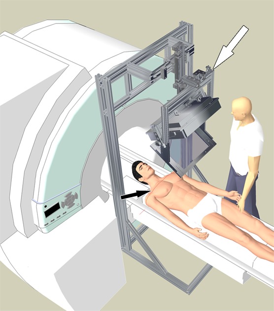
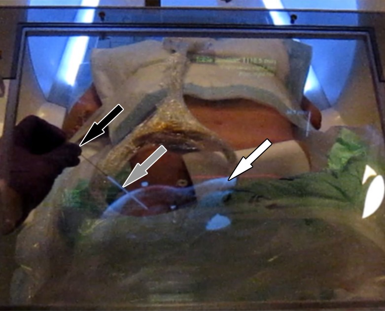
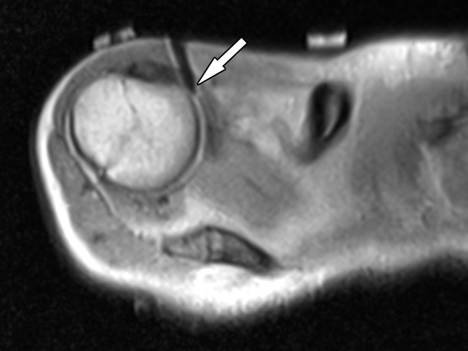
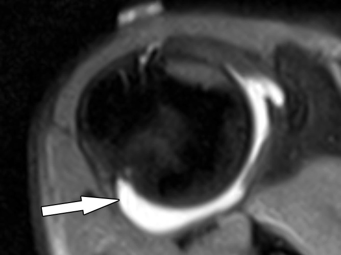
Purpose: To prospectively assess overlay technology in providing accurate and efficient targeting for magnetic resonance (MR) imaging-guided shoulder and hip joint arthrography.

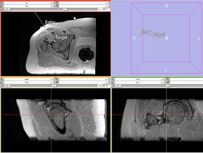
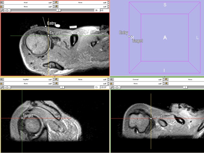
Materials and methods: A prototype augmented reality image overlay system was used in conjunction with a clinical 1.5-T MR imager. A total of 24 shoulder joint and 24 hip joint injections were planned in 12 human cadavers. Two operators (A and B) participated, each performing procedures on different cadavers using image overlay guidance. MR imaging was used to confirm needle positions, monitor injections, and perform MR arthrography. Accuracy was assessed according to the rate of needle adjustment, target error, and whether the injection was intraarticular. Efficiency was assessed according to arthrography procedural time. Operator differences were assessed with comparison of accuracy and procedure times between the operators. Mann-Whitney U test and Fisher exact test were used to assess group differences.

Results: Forty-five arthrography procedures (23 shoulders, 22 hips) were performed. Three joints had prostheses and were excluded. Operator A performed 12 shoulder and 12 hip injections. Operator B performed 11 shoulder and 10 hip injections. Needle adjustment rate was 13% (six of 45; one for operator A and five for operator B). Target error was 3.1 mm±1.2 (standard deviation) (operator A, 2.9 mm±1.4; operator B, 3.5 mm±0.9). Intraarticular injection rate was 100% (45 of 45). The average arthrography time was 14 minutes (range, 6-27 minutes; 12 minutes [range, 6-25 minutes] for operator A and 16 minutes [range, 6-27 min] for operator B). Operator differences were not significant with regard to needle adjustment rate (P=.08), target error (P=.07), intraarticular injection rate (P>.99), and arthrography time (P=.22).

Conclusion: Image overlay technology provides accurate and efficient MR guidance for successful shoulder and hip arthrography in human cadavers.


Figures

Figure 1a:
Figure 1a:
(a) Schematic depiction of the interventional setup of the AR image overlay prototype system (white arrow) in conjunction with a clinical 1.5-T MR imaging system. The red laser line (black arrow) on the subject’s skin coincides with the selected MR image target. (b) Planning of the needle path to the femoral head-neck junction with three-dimensional SPACE MR imaging (1100/100; flip angle, 120°; two signals acquired; echo train length, 117; voxel size, 1 × 1 × 1 mm; number of sections, 60; field of view, 256 × 224 mm; base resolution, 192 pixels; phase resolution, 100%; bandwidth, 751 Hz; acquisition time, 5 minutes 43 seconds) data set. Top left: Axial reformation. Top right: Three-dimensional map. Bottom left: Sagittal reformation. Bottom right: Coronal reformation. A = anterior, R = right, L = left, S = superior, I = inferior. (c) Intraprocedural photograph of MR-guided injection of the right hip with image overlay system, from the operator’s view. The target MR image (white arrow) is fused with a graphical representation of the planned needle path and depth (gray arrow). The skin entry point is indicated by the apparent intersection of the red laser line and the virtual needle path. Black arrow = operator’s hand while inserting the needle (Movie 1 [online]).
Figure 1b:
Figure 1b:
(a) Schematic depiction of the interventional setup of the AR image overlay prototype system (white arrow) in conjunction with a clinical 1.5-T MR imaging system. The red laser line (black arrow) on the subject’s skin coincides with the selected MR image target. (b) Planning of the needle path to the femoral head-neck junction with three-dimensional SPACE MR imaging (1100/100; flip angle, 120°; two signals acquired; echo train length, 117; voxel size, 1 × 1 × 1 mm; number of sections, 60; field of view, 256 × 224 mm; base resolution, 192 pixels; phase resolution, 100%; bandwidth, 751 Hz; acquisition time, 5 minutes 43 seconds) data set. Top left: Axial reformation. Top right: Three-dimensional map. Bottom left: Sagittal reformation. Bottom right: Coronal reformation. A = anterior, R = right, L = left, S = superior, I = inferior. (c) Intraprocedural photograph of MR-guided injection of the right hip with image overlay system, from the operator’s view. The target MR image (white arrow) is fused with a graphical representation of the planned needle path and depth (gray arrow). The skin entry point is indicated by the apparent intersection of the red laser line and the virtual needle path. Black arrow = operator’s hand while inserting the needle (Movie 1 [online]).
Figure 1c:
Figure 1c:
(a) Schematic depiction of the interventional setup of the AR image overlay prototype system (white arrow) in conjunction with a clinical 1.5-T MR imaging system. The red laser line (black arrow) on the subject’s skin coincides with the selected MR image target. (b) Planning of the needle path to the femoral head-neck junction with three-dimensional SPACE MR imaging (1100/100; flip angle, 120°; two signals acquired; echo train length, 117; voxel size, 1 × 1 × 1 mm; number of sections, 60; field of view, 256 × 224 mm; base resolution, 192 pixels; phase resolution, 100%; bandwidth, 751 Hz; acquisition time, 5 minutes 43 seconds) data set. Top left: Axial reformation. Top right: Three-dimensional map. Bottom left: Sagittal reformation. Bottom right: Coronal reformation. A = anterior, R = right, L = left, S = superior, I = inferior. (c) Intraprocedural photograph of MR-guided injection of the right hip with image overlay system, from the operator’s view. The target MR image (white arrow) is fused with a graphical representation of the planned needle path and depth (gray arrow). The skin entry point is indicated by the apparent intersection of the red laser line and the virtual needle path. Black arrow = operator’s hand while inserting the needle (Movie 1 [online]).
Figure 2a:
Figure 2a:
Image overlay MR-guided injection and arthrography of the right shoulder. (a) Planning of the needle path through the rotator interval with three-dimensional SPACE MR imaging (1000/34; flip angle, 120°; two signals acquired; echo train length, 49; voxel size, 1 × 1 × 1 mm; number of sections, 60; field of view, 192 × 168 mm; base resolution, 192 pixesl; phase resolution, 100%; bandwidth, 744 Hz; acquisition time, 2 minutes 55 seconds) data set. Top left: Axial reformation. Top right: Three-dimensional map. Bottom left: Sagittal reformation. Bottom right: Coronal reformation. A = anterior, R = right, L = left, S = superior, I = inferior. (b) Axial intermediate-weighted turbo spin-echo MR image shows the needle tip (arrow) at the target location. (c) Axial T1-weighted diagnostic MR arthrogram with intraarticular contrast agent (arrow) following joint injection (Movie 2 [online]).
Figure 2b:
Figure 2b:
Image overlay MR-guided injection and arthrography of the right shoulder. (a) Planning of the needle path through the rotator interval with three-dimensional SPACE MR imaging (1000/34; flip angle, 120°; two signals acquired; echo train length, 49; voxel size, 1 × 1 × 1 mm; number of sections, 60; field of view, 192 × 168 mm; base resolution, 192 pixesl; phase resolution, 100%; bandwidth, 744 Hz; acquisition time, 2 minutes 55 seconds) data set. Top left: Axial reformation. Top right: Three-dimensional map. Bottom left: Sagittal reformation. Bottom right: Coronal reformation. A = anterior, R = right, L = left, S = superior, I = inferior. (b) Axial intermediate-weighted turbo spin-echo MR image shows the needle tip (arrow) at the target location. (c) Axial T1-weighted diagnostic MR arthrogram with intraarticular contrast agent (arrow) following joint injection (Movie 2 [online]).
Figure 2c:
Figure 2c:
Image overlay MR-guided injection and arthrography of the right shoulder. (a) Planning of the needle path through the rotator interval with three-dimensional SPACE MR imaging (1000/34; flip angle, 120°; two signals acquired; echo train length, 49; voxel size, 1 × 1 × 1 mm; number of sections, 60; field of view, 192 × 168 mm; base resolution, 192 pixesl; phase resolution, 100%; bandwidth, 744 Hz; acquisition time, 2 minutes 55 seconds) data set. Top left: Axial reformation. Top right: Three-dimensional map. Bottom left: Sagittal reformation. Bottom right: Coronal reformation. A = anterior, R = right, L = left, S = superior, I = inferior. (b) Axial intermediate-weighted turbo spin-echo MR image shows the needle tip (arrow) at the target location. (c) Axial T1-weighted diagnostic MR arthrogram with intraarticular contrast agent (arrow) following joint injection (Movie 2 [online]).

Similar articles

Cited by

References

    1. Miller TT. MR arthrography of the shoulder and hip after fluoroscopic landmarking. Skeletal Radiol 2000;29(2):81–84 - PubMed
    1. Mulligan ME. CT-guided shoulder arthrography at the rotator cuff interval. AJR Am J Roentgenol 2008;191(2):W58–W61 - PubMed
    1. Dépelteau H, Bureau NJ, Cardinal E, Aubin B, Brassard P. Arthrography of the shoulder: a simple fluoroscopically guided approach for targeting the rotator cuff interval. AJR Am J Roentgenol 2004;182(2):329–332 - PubMed
    1. Steinbach LS, Palmer WE, Schweitzer ME. Special focus session: MR arthrography. RadioGraphics 2002;22(5):1223–1246 - PubMed
    1. Nawfel RD, Judy PF, Silverman SG, Hooton S, Tuncali K, Adams DF. Patient and personnel exposure during CT fluoroscopy-guided interventional procedures. Radiology 2000;216(1):180–184 - PubMed

LinkOut - more resources