. 2011 Aug 6;1(4):477-89.
doi: 10.1098/rsfs.2011.0027. Epub 2011 May 18.

Medical ultrasound systems

Affiliations

Medical ultrasound systems

Jeff Powers et al. Interface Focus. .

Abstract

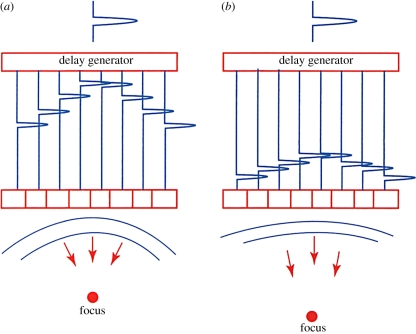
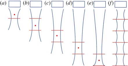
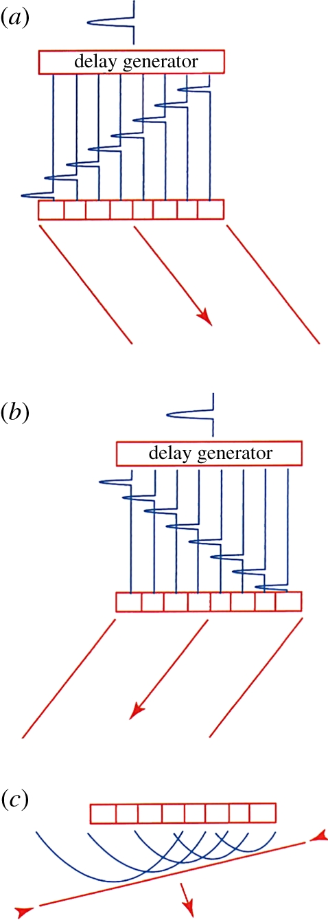
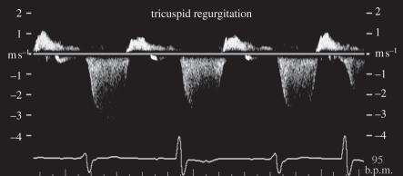
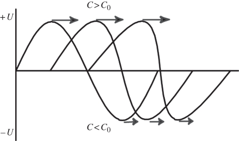
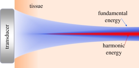
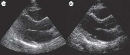
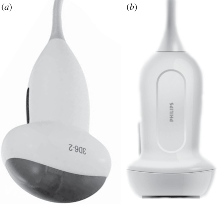
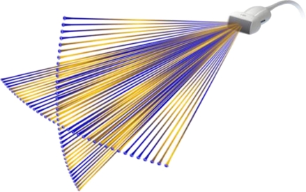
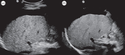
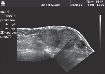
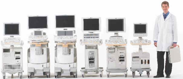
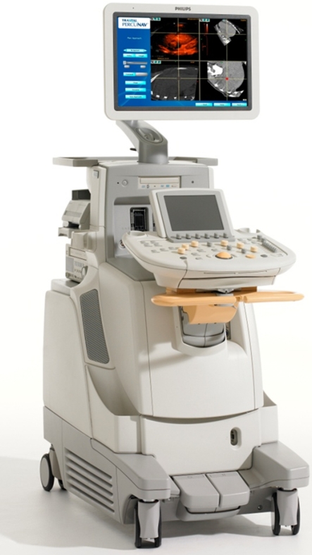
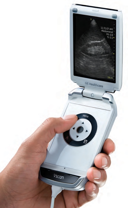
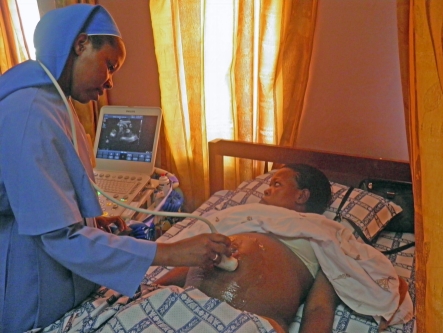
Medical ultrasound imaging has advanced dramatically since its introduction only a few decades ago. This paper provides a short historical background, and then briefly describes many of the system features and concepts required in a modern commercial ultrasound system. The topics addressed include array beam formation, steering and focusing; array and matrix transducers; echo image formation; tissue harmonic imaging; speckle reduction through frequency and spatial compounding, and image processing; tissue aberration; Doppler flow detection; and system architectures. It then describes some of the more practical aspects of ultrasound system design necessary to be taken into account for today's marketplace. It finally discusses the recent explosion of portable and handheld devices and their potential to expand the clinical footprint of ultrasound into regions of the world where medical care is practically non-existent. Throughout the article reference is made to ways in which ultrasound imaging has benefited from advances in the commercial electronics industry. It is meant to be an overview of the field as an introduction to other more detailed papers in this special issue.

Keywords: medical; systems; ultrasound.


Figures

Figure 1.
Figure 1.
M-mode echocardiogram showing cardiac wall motion over time. (From Kremkau [1].)
Figure 2.
Figure 2.
(a) A single amplitude (A-mode) line is used to produce a B-mode image (b) when swept throughout the scan plane. (From Kremkau [1].)
Figure 3.
Figure 3.
Early mechanically scanned transducer with the motor in the handle and three belt-driven transducers on the wheel.
Figure 4.
Figure 4.
Linear array scan showing (a) transducer and scan plane geometry; (b) early OB linear array image showing vertical scan lines; and (c) a modern linear array image. (From Kremkau [1].)
Figure 5.
Figure 5.
Array focusing showing delays for close focus (a) and far focus (b). (From Kremkau [1].)
Figure 6.
Figure 6.
Multi-zone focus showing: (ae) progressively deeper focus; (f) uniform focus achieved by blending focal zones. (From Kremkau [1].)
Figure 7.
Figure 7.
Array steering: (a) delays for steering right; (b) delays for steering left; and (c) wavefronts producing a steered wave. (From Kremkau [1].)
Figure 8.
Figure 8.
Pulsed wave Doppler showing regurgitant flow in a tricuspid valve.
Figure 9.
Figure 9.
Cartid colour and pulsed wave Doppler showing spectrum without (left) and with (right) angle correction on a frozen image (cursor highlighted in cyan for visibility).
Figure 10.
Figure 10.
Carotid bifurcation showing complex velocity patterns in a colour flow image.
Figure 11.
Figure 11.
Phased array elements compared with the size of a human hair.
Figure 12.
Figure 12.
Matrix array elements compared with a human hair.
Figure 13.
Figure 13.
Philips X7-2 matrix transducer for imaging the heart in three dimensions in real time from within the oesophagus.
Figure 14.
Figure 14.
Three-dimensional images of an aortic valve acquired in real time from inside the oesophagus with the Philips X7-2 TEE transducer (a) in diastole and (b) in systole.
Figure 15.
Figure 15.
(a) Conventional linear array scan and (b) spatial compounding scan. Image volume is scanned from multiple directions, reducing coherent speckle. The best results are obtained in the centre of the image, where the volume is scanned from the most different directions. (From Kremkau [1].)
Figure 16.
Figure 16.
(a) Conventional image and frequency compounded, or SonoCT, (b) image showing the reduced coherent speckle without a reduction in spatial resolution.
Figure 17.
Figure 17.
Tissue harmonic generation: as the wave propagates, the higher pressure portion of the wave travels faster owing to the higher density of the medium and the lower pressure travels slower, leading to wave distortion and harmonic generation.
Figure 18.
Figure 18.
Harmonic energy is only created in the central, most intense portion of the beam, resulting in a narrower beam and improved spatial resolution.
Figure 19.
Figure 19.
(a) Fundamental and (b) tissue harmonic images of a difficult cardiac patient showing reduced clutter and improved tissue resolution.
Figure 20.
Figure 20.
Three-dimensional imaging transducers showing the (a) 3D 6-2 mechanically oscillating array and (b) the X6-1 matrix transducer.
Figure 21.
Figure 21.
X-plane scanning format using a two-dimensional matrix array. Any planes may be imaged simultaneously.
Figure 22.
Figure 22.
Philips X6-1 liver scan comparing (a) conventional imaging and (b) X-Matrix thin slice imaging.
Figure 23.
Figure 23.
Panoramic image showing increased near-field image width.
Figure 24.
Figure 24.
Philips family of ultrasound systems.
Figure 25.
Figure 25.
Philips iU22 ultrasound system.
Figure 26.
Figure 26.
VScan handheld ultrasound system from GE. (From Kremkau [1].)
Figure 27.
Figure 27.
Compact CX50 in use in a medical clinic in Uganda. Courtesy of Imaging the World.

References

    1. Kremkau F. W. 2011. Sonography prinicples and instruments, pp. 292, 8th edn. Amsterdam, The Netherlands: Elsevier Saunders
    1. Wells P. N. 1988. Ultrasound imaging. J. Biomed. Eng. 10, 548–55410.1016/0141-5425(88)90114-8 (doi:10.1016/0141-5425(88)90114-8) - DOI - DOI - PubMed
    1. Flax S. W., O'Donnell M. 1988. Phase-aberration correction using signals from point reflectors and diffuse scatterers: basic principles. IEEE Trans. Ultrason. Ferroelectr. Freq. Control 35, 758–76710.1109/58.9333 (doi:10.1109/58.9333) - DOI - DOI - PubMed
    1. Nock L., Trahey G. E., Smith S. W. 1989. Phase aberration correction in medical ultrasound using speckle brightness as a quality factor. J. Acoust. Soc. Am. 85, 1819–183310.1121/1.397889 (doi:10.1121/1.397889) - DOI - DOI - PubMed
    1. O'Donnell M., Flax S. W. 1988. Phase-aberration correction using signals from point reflectors and diffuse scatterers: measurements. IEEE Trans. Ultrason. Ferroelectr. Freq. Control 35, 768–77410.1109/58.9334 (doi:10.1109/58.9334) - DOI - DOI - PubMed

LinkOut - more resources