. 2011 Aug 6;1(4):503-19.
doi: 10.1098/rsfs.2011.0019. Epub 2011 Jun 1.

Three-dimensional ultrasound scanning

Affiliations

Three-dimensional ultrasound scanning

Aaron Fenster et al. Interface Focus. .

Abstract

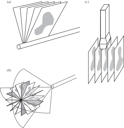
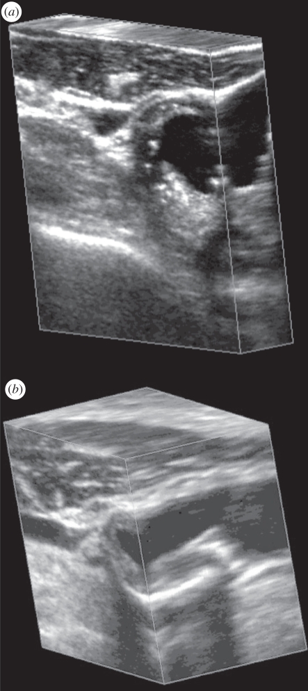
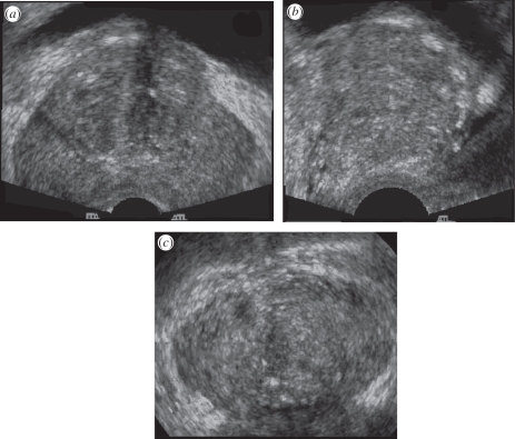
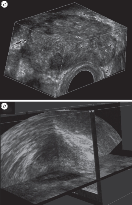
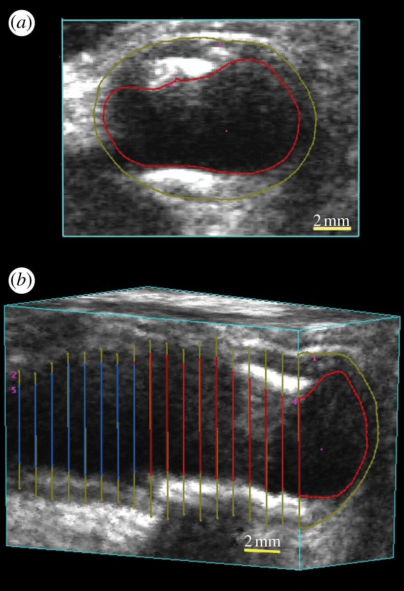
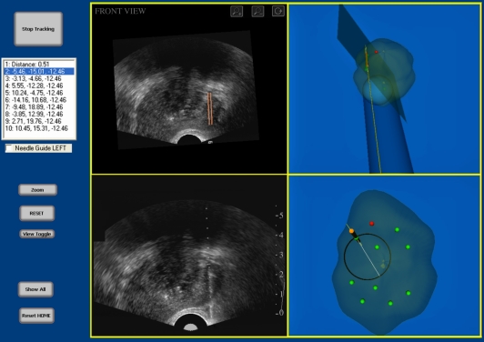
The past two decades have witnessed developments of new imaging techniques that provide three-dimensional images about the interior of the human body in a manner never before available. Ultrasound (US) imaging is an important cost-effective technique used routinely in the management of a number of diseases. However, two-dimensional viewing of three-dimensional anatomy, using conventional two-dimensional US, limits our ability to quantify and visualize the anatomy and guide therapy, because multiple two-dimensional images must be integrated mentally. This practice is inefficient, and may lead to variability and incorrect diagnoses. Investigators and companies have addressed these limitations by developing three-dimensional US techniques. Thus, in this paper, we review the various techniques that are in current use in three-dimensional US imaging systems, with a particular emphasis placed on the geometric accuracy of the generation of three-dimensional images. The principles involved in three-dimensional US imaging are then illustrated with a diagnostic and an interventional application: (i) three-dimensional carotid US imaging for quantification and monitoring of carotid atherosclerosis and (ii) three-dimensional US-guided prostate biopsy.

Keywords: computed tomography; radiographic imaging; three-dimensional ultrasound scanning.


Figures

Figure 1.
Figure 1.
Schematic diagram of three-dimensional ultrasound (US) mechanical scanning methods. (a) Side-firing transrectal US transducer being mechanically rotated. The acquired images have equal angular spacing. The same approach is used in a mechanically wobbled transducer. (b) A rotational scanning mechanism, typically used in three-dimensional US-guided prostate biopsy. The acquired images have equal angular spacing. (c) Linear mechanical scanning mechanism. The acquired images have equal spacing.
Figure 2.
Figure 2.
Two examples of three-dimensional US images of the carotid arteries obtained with the mechanical linear three-dimensional scanning approach. The three-dimensional US images are displayed using the cube-view approach and have been sliced to reveal the details of the atherosclerotic plaque in the carotid arteries in transverse and longitudinal views.
Figure 3.
Figure 3.
A three-dimensional US image of the prostate acquired using an endocavity rotational three-dimensional scanning approach (rotation of a transrectal US transducer). The transducer was rotated around its long axis, while three-dimensional US images were acquired and reconstructed. The three-dimensional US image using an end-firing transducer is displayed using the cube-view approach and has been sliced to reveal: (a) a transverse view, (b) a sagittal view and (c) a coronal view, not possible using conventional two-dimensional US techniques.
Figure 4.
Figure 4.
The three-dimensional US of the prostate displayed using (a) the cube-view and (b) the crossed planes approaches. The three-dimensional US images were acquired using a side-firing transducer using the mechanical rotation approach.
Figure 5.
Figure 5.
Three-dimensional US rectal images obtained by the mechanical rotational mechanism, which rotated a side-firing transrectal ultrasound (TRUS) transducer around its long axis by 180°. The three-dimensional US images are viewed using the multi-planar formatting approach. (a) Clear delineation of the rectal wall. (b) Three-dimensional view of the sphincter muscles. (c) Three-dimensional view of a rectal polyp—stage T1, with the polyp invading the submucosa. (d) Three-dimensional view of a rectal polyp—stage 2, with the polyp invading the muscularis propria, but not beyond.
Figure 6.
Figure 6.
Two three-dimensional US images that have been volume rendered. (a) Three-dimensional US image of a foetal face. (b) Three-dimensional US image of the vasculature in a kidney obtained using free-hand three-dimensional Doppler scanning.
Figure 7.
Figure 7.
(a) Photograph of a mechanical linear scanning mechanism used to acquire three-dimensional carotid US images. The transducer is translated along the arteries, while conventional two-dimensional US images are acquired by a computer and reconstructed into a three-dimensional image in real time. (b) Photograph of the system being used to scan the carotid arteries.
Figure 8.
Figure 8.
An example of a three-dimensional carotid US image of a patient with carotid atherosclerosis.
Figure 9.
Figure 9.
(a) Three-dimensional views of VWV measurements. The three-dimensional image is ‘sliced’ to obtain a transverse view. Using a mouse-driven cross-haired cursor, the plaque is outlined in successive image ‘slices’ until all the plaques have been traversed. (b) The vessel can be sliced to reveal a longitudinal view with the outlines of the plaques. After outlining all the plaques, the total volume can be calculated and a mesh fitted to provide a view of the plaque surface together with the boundary of the vessel.
Figure 10.
Figure 10.
Photograph of the three-dimensional US-guided prostate biopsy tracking system. The system is mounted at the base to a stabilizer while the linkage allows the conventional end-firing TRUS transducer to be manually manipulated about a fixed point in space, to which the centre of the probe tip is aligned. To produce a three-dimensional US image, the transducer is rotated about its long axis for 180°.
Figure 11.
Figure 11.
The display for viewing the three-dimensional US image of the prostate and to perform the segmentation of the prostate. The user can verify that the prostate has been segmented accurately and perform any required edits to the boundary.
Figure 12.
Figure 12.
The three-dimensional US-guided prostate biopsy system interface is composed of four windows: (top left) the three-dimensional TRUS image sliced to match the real-time TRUS probe orientation; (bottom left) the live two-dimensional TRUS video stream; and (right side) the three-dimensional location of the biopsy core within the three-dimensional prostate model. The targeting ring in the bottom right window shows all the possible needle paths that intersect the preplanned target by rotating the TRUS about its long axis.

References

    1. Elliott S. T. 2008. Volume ultrasound: the next big thing? Br. J. Radiol. 81, 8–910.1259/bjr/13475432 (doi:10.1259/bjr/13475432) - DOI - DOI - PubMed
    1. Downey D. B., Fenster A., Williams J. C. 2000. Clinical utility of three-dimensional US. Radiographics 20, 559–571 - PubMed
    1. Boctor E. M., Choti M. A., Burdette E. C., Webster R. J., III 2008. Three-dimensional ultrasound-guided robotic needle placement: an experimental evaluation. Int. J. Med. Robot. 4, 180–191 - PMC - PubMed
    1. Hummel J., Figl M., Bax M., Bergmann H., Birkfellner W. 2008. 2D/3D registration of endoscopic ultrasound to CT volume data. Phys. Med. Biol. 53, 4303–431610.1088/0031-9155/53/16/006 (doi:10.1088/0031-9155/53/16/006) - DOI - DOI - PubMed
    1. Carson P. L., Fenster A. 2009. Anniversary paper: evolution of ultrasound physics and the role of medical physicists and the AAPM and its journal in that evolution. Med. Phys. 36, 411–42810.1118/1.2992048 (doi:10.1118/1.2992048) - DOI - DOI - PubMed

LinkOut - more resources