. 2011 Aug 6;1(4):602-31.
doi: 10.1098/rsfs.2011.0028. Epub 2011 Jun 22.

Biomedical photoacoustic imaging

Affiliations

Biomedical photoacoustic imaging

Paul Beard. Interface Focus. .

Abstract

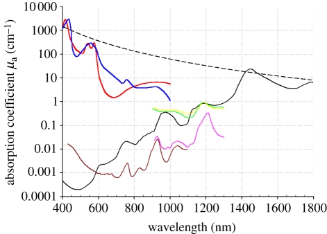
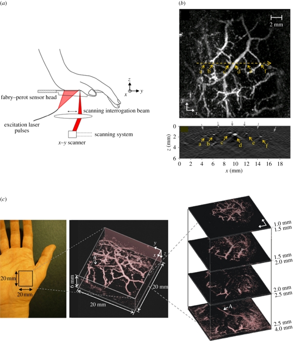
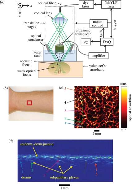
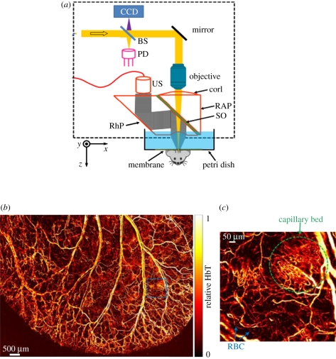
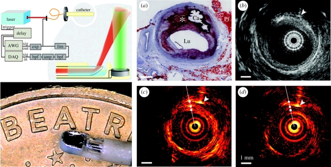
Photoacoustic (PA) imaging, also called optoacoustic imaging, is a new biomedical imaging modality based on the use of laser-generated ultrasound that has emerged over the last decade. It is a hybrid modality, combining the high-contrast and spectroscopic-based specificity of optical imaging with the high spatial resolution of ultrasound imaging. In essence, a PA image can be regarded as an ultrasound image in which the contrast depends not on the mechanical and elastic properties of the tissue, but its optical properties, specifically optical absorption. As a consequence, it offers greater specificity than conventional ultrasound imaging with the ability to detect haemoglobin, lipids, water and other light-absorbing chomophores, but with greater penetration depth than purely optical imaging modalities that rely on ballistic photons. As well as visualizing anatomical structures such as the microvasculature, it can also provide functional information in the form of blood oxygenation, blood flow and temperature. All of this can be achieved over a wide range of length scales from micrometres to centimetres with scalable spatial resolution. These attributes lend PA imaging to a wide variety of applications in clinical medicine, preclinical research and basic biology for studying cancer, cardiovascular disease, abnormalities of the microcirculation and other conditions. With the emergence of a variety of truly compelling in vivo images obtained by a number of groups around the world in the last 2-3 years, the technique has come of age and the promise of PA imaging is now beginning to be realized. Recent highlights include the demonstration of whole-body small-animal imaging, the first demonstrations of molecular imaging, the introduction of new microscopy modes and the first steps towards clinical breast imaging being taken as well as a myriad of in vivo preclinical imaging studies. In this article, the underlying physical principles of the technique, its practical implementation, and a range of clinical and preclinical applications are reviewed.

Keywords: biomedical; imaging; medical; photoacoustic; ultrasound.


Figures

Figure 1.
Figure 1.
Absorption coefficient spectra of endogenous tissue chromophores. Oxyhaemoglobin (HbO2), red line: (http://omlc.ogi.edu/spectra/hemoglobin/summary.html; 150 gl−1), deoxyhaemoglobin (HHb), blue line: (http://omlc.ogi.edu/spectra/hemoglobin/summary.html; 150 gl−1), water, black line [22] (80% by volume in tissue), lipid(a), brown line [23] (20% by volume in tissue), lipid(b), pink line [24], melanin, black dashed line (http://omlc.ogi.edu/spectra/melanin/mua.html; μa corresponds to that in skin). Collagen (green line) and elastin (yellow line) spectra from [24].
Figure 2.
Figure 2.
PAT detection geometries. (a) Spherical, (b) cylindrical and (c) planar.
Figure 3.
Figure 3.
Backprojection PAT image reconstruction for a planar detection geometry. PA waveforms are recorded by each array element at r, spatially resolved using the sound speed c and backprojected over spherical surfaces of radius R = ct into the image volume. Since the backprojected quantity is the velocity potential, the output of each detector is depicted as a time-integrated pressure waveform for illustrative purposes—in practice, the detectors record a pressure waveform and the time integration is performed computationally.
Figure 4.
Figure 4.
PAT breast scanner with hemispherical detection geometry [27]. (a) Schematic of system. (b) MIP of the left breast of patient volunteer (lateral projection) over 64 × 50 mm2 FOV. Arrows at top indicate the direction of the incident excitation light. Hollow arrow marks the position of a vessel at a depth of 40 mm. Hollow box represents 1 × 1 cm2 (c) orthogonal (anterior–posterior) projection 64 × 64 mm2 FOV. Excitation laser wavelength: 800 nm. Three-dimensional animated MIP movies of both projections can be viewed online at the electronic supplementary material, movies S1 and S2.
Figure 5.
Figure 5.
PAT whole body small animal scanner based on a spherical detection geometry [62]. (a) Experimental arrangement showing 64 element arc array and fibre delivery bundle. (b) Three-dimensional image of a nude mouse illuminated at 755 nm. Both kidneys are visualized as well as the spleen and a partial lobe of the liver. (c) Image showing spinal region and left and right kidneys. Three-dimensional-animated movies of the two images can be viewed online at electronic supplementary material, movies S3–S5.
Figure 6.
Figure 6.
PAT cylindrical scanner for small animal brain imaging [64] (a) experimental arrangement. (b) Image showing superficial cortical vasculature and a surgically induced lesion. MCA: middle cerebral artery, RH: right cerebral hemisphere, LH: left cerebral hemisphere. (c) Photograph of cerebral surface following resection of the skull after PAT image acquisition. Laser wavelength: 532 nm.
Figure 7.
Figure 7.
Use of a conventional ultrasound imaging probe for PA imaging. (a) Two-dimensional array probe. (b) Implementation using a linear array probe for dual mode PAT-US imaging described in Kim et al. [29].
Figure 8.
Figure 8.
(left) In vivo PAT images and (right) corresponding US images of a vein at the interior part of the medial lower leg obtained using a linear ultrasound array [44]. The image area is 2.6×2 cm (ticks every centimetre) (a) Cross-sectional image from the interior part of the leg. In the PAT image (left), the skin (S) is visible as a black line. Black and white arrows identify the location of common blood vessels observed in both PAT and US images (b) Images acquired at the same location but in the orthogonal plane. Laser wavelength: 760 nm.
Figure 9.
Figure 9.
(a) Schematic of FP-based photoacoustic scanner used to acquire a three-dimensional image of the vasculature in the palm [45]. (b) Lateral MIP image (top) and vertical (xz) slice image (bottom) taken along horizontal yellow dotted line on MIP. Grey arrows indicate the contour of the skin surface. (c) Left: photograph of the imaged region, middle: volume rendered image. An animated representation of this image can be viewed online at electronic supplementary material, movie S6, and right: lateral slices at different depths. The arrow ‘A’ indicates the deepest visible vessel, which is located 4 mm beneath the surface of the skin. Laser excitation wavelength: 670 nm.
Figure 10.
Figure 10.
Acoustic-resolution photoacoustic microscopy (AR-PAM) system used for imaging the skin vasculature [94]. (a) Schematic of system, (b) region of forearm scanned, (c) lateral xy MIP image (FOV = 8 × 8 mm), (d) vertical xz slice image taken along vertical line in (c). Laser excitation wavelength: 584 nm.
Figure 11.
Figure 11.
Optical-resolution photoacoustic microscopy (OR-PAM) scanner used for in vivo imaging of the mouse ear [118]. (a) Schematic of system BS, beam splitter; PD, photodiode; CorL, correction lens; RAP, right-angle prism; SO, silicone oil; RhP, rhomboid prism; US, ultrasonic transducer (50 MHz). The CCD is used to view the imaging region. The components that lie within the dotted rectangle form the scan head, which is mechanically translated in order to acquire an image. (b) In vivo image of the microvasculature in the mouse ear. (c) Expanded region shows capillary network and red blood cells (RBC) within a capillary. Excitation wavelength: 570 nm.
Figure 12.
Figure 12.
Dual mode intravascular PA and US imaging probe used to image ex vivo human coronary arteries [127]. Left panel: (upper) schematic of experimental set-up. (lower) photograph of distal end of catheter. Right panel: (a) Histological section showing a lipid-rich plaque (asterisk) and a region of calcification (Ca). Lu, lumen; Pf, peri-adventitial fat. (b) IVUS image, (c) intravascular PA image obtained using an excitation wavelength of 1210 nm (high lipid absorption) and (d) intravascular PA image obtained using an excitation wavelength of 1230 nm (low lipid absorption).
Figure 13.
Figure 13.
Photoacoustic imaging of lipid-rich atheromatous plaques [132]. (a) Photograph of human aorta sample with raised plaque. The horizontal dotted line represents the photoacoustic scan line. (b) Two-dimensional photoacoustic image obtained at 970 nm (low lipid absorption), (c) photoacoustic image obtained at 1200 nm (high lipid absorption) showing the high contrast owing to increased lipid content within plaque.
Figure 14.
Figure 14.
Combined ultrasound and PA imaging of a coronary artery stent embedded in a tissue phantom [173]. (a) Ultrasound image, (b) photoacoustic image, (c) fused ultrasound and photoacoustic image.
Figure 15.
Figure 15.
In vivo photoacoustic ocular imaging: (a) PA vertical B-scan image acquired along the horizontal red line in (c) showing retinal blood vessel and the underlying retinal pigment epithelium (RPE) in the rat eye [120]. (b) OCT image acquired simultaneously showing corresponding features [120], (c) lateral MIP showing the retinal vasculature over the optic disc. HA signifies shadowing owing to hyaloid artery remnant [120]. (d) Lateral MIP image of iris vasculature in mouse eye [121]. Dual wavelength spectroscopy was used to map oxygen saturation over the rectangular region indicated by the yellow dotted outline. (d) CP, ciliary process; MIC, major iris circle; RCB, recurrent choroidal branch and RIA, radial iris artery.

References

    1. Bell A. G. 1880. On the production and reproduction of sound by light. Am. J. Sci. 20, 305–324.
    1. Tam A. 1986. Applications of photoacoustic sensing techniques. Rev. Mod. Phys. 58, 381–431.10.1103/RevModPhys.58.381 (10.1103/RevModPhys.58.381) - DOI - DOI
    1. Kruger R., Liu P., Appledorn C. 1995. Photoacoustic ultrasound (PAUS)—reconstruction tomography. Med. Phys. 22, 1605–1609.10.1118/1.597429 (10.1118/1.597429) - DOI - DOI - PubMed
    1. Esenaliev R. O., Karabutov A. A., Tittel F. K., Fornage B. D., Thomsen S. L., Stelling C., Oraevsky A. A. 1997. Laser optoacoustic imaging for breast cancer diagnostics: limit of detection and comparison with x-ray and ultrasound imaging. Proc. SPIE 2979, 71–82.10.1117/12.280213 (10.1117/12.280213) - DOI - DOI
    1. Hoelen C. G., de Mul F. F., Pongers R., Dekker A. 1998. Three-dimensional photoacoustic imaging of blood vessels in tissue. Opt. Lett. 23, 648–650.10.1364/OL.23.000648 (10.1364/OL.23.000648) - DOI - DOI - PubMed

LinkOut - more resources