. 2012 Aug 1;3(8):1774-86.
doi: 10.1364/BOE.3.001774. Epub 2012 Jun 29.

Motion correction of in vivo three-dimensional optical coherence tomography of human skin using a fiducial marker

Motion correction of in vivo three-dimensional optical coherence tomography of human skin using a fiducial marker

Yih Miin Liew et al. Biomed Opt Express. .

Abstract

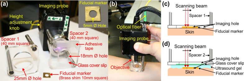
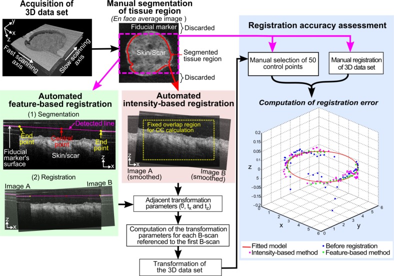
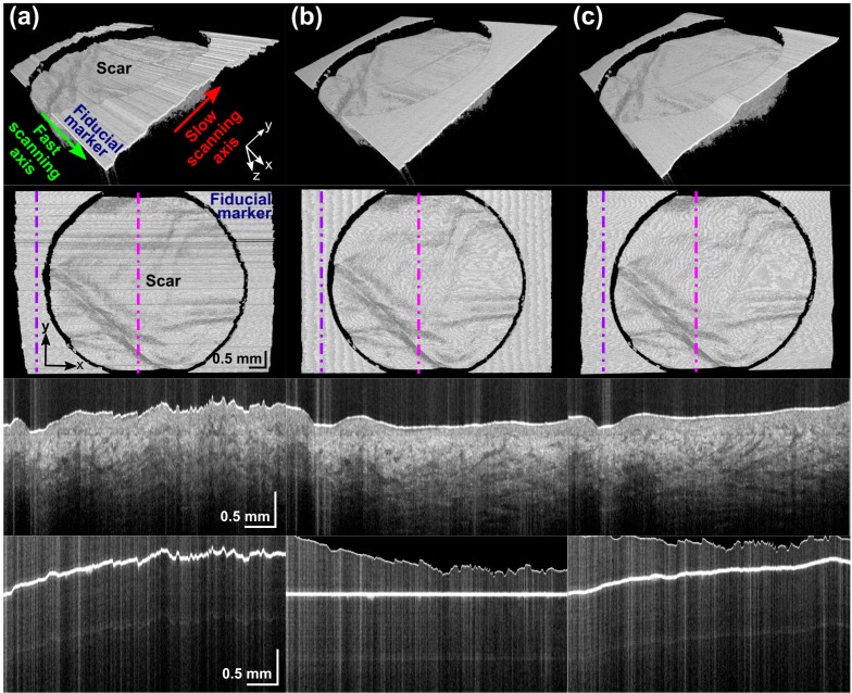
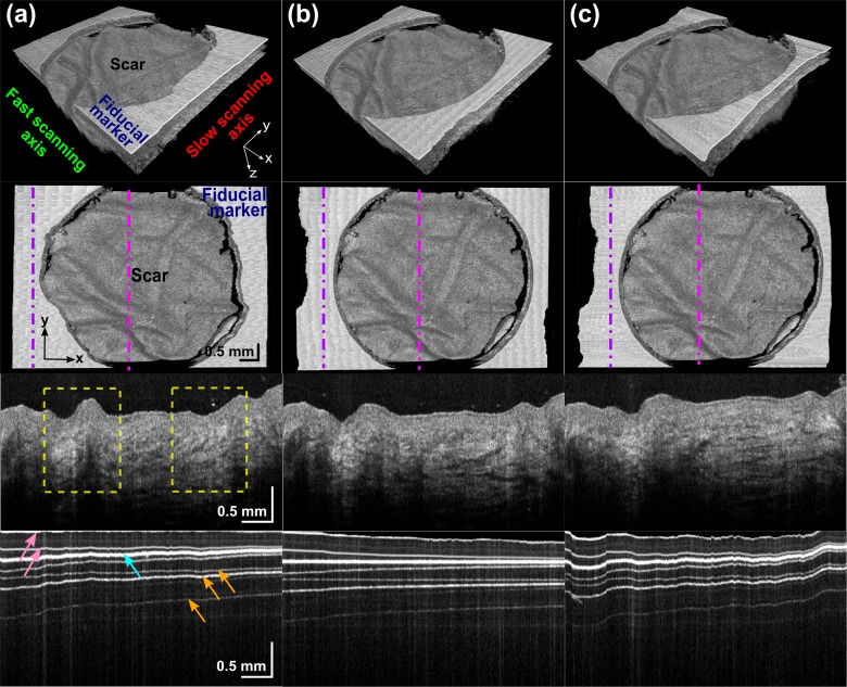
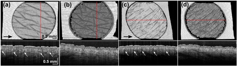
This paper presents a novel method based on a fiducial marker for correction of motion artifacts in 3D, in vivo, optical coherence tomography (OCT) scans of human skin and skin scars. The efficacy of this method was compared against a standard cross-correlation intensity-based registration method. With a fiducial marker adhered to the skin, OCT scans were acquired using two imaging protocols: direct imaging from air into tissue; and imaging through ultrasound gel into tissue, which minimized the refractive index mismatch at the tissue surface. The registration methods were assessed with data from both imaging protocols and showed reduced distortion of skin features due to motion. The fiducial-based method was found to be more accurate and robust, with an average RMS error below 20 µm and success rate above 90%. In contrast, the intensity-based method had an average RMS error ranging from 36 to 45 µm, and a success rate from 50% to 86%. The intensity-based algorithm was found to be particularly confounded by corrugations in the skin. By contrast, tissue features did not affect the fiducial-based method, as the motion correction was based on delineation of the flat fiducial marker. The average computation time for the fiducial-based algorithm was approximately 21 times less than for the intensity-based algorithm.

Keywords: (100.2000) Digital image processing; (100.6950) Tomographic image processing; (170.4500) Optical coherence tomography.


Figures

Fig. 1
Fig. 1
Handheld SS-OCT probe and sample spacer setups for in vivo imaging of skin. (a) Photograph of the imaging probe setup showing interchangeable sample spacers. (b) Photograph of the handheld probe in use. (c) Schematic diagram of imaging protocol in air. (d) Schematic diagram of imaging protocol in RI-matching medium (ultrasound gel).
Fig. 2
Fig. 2
Flow diagram for the comparison of feature-based and intensity-based registration methods.
Fig. 3
Fig. 3
Typical results for an air-tissue data set: (a) before registration; (b) after feature-based registration; and (c) after intensity-based registration. For each of (a), (b), and (c): 3D solid render side view (Row 1) and top view (Row 2); a slow-axis B-scan across the scar (Row 3); and fiducial marker (Row 4) at positions indicated by the magenta and purple dot-dashed lines, respectively.
Fig. 4
Fig. 4
Typical results for a gel-tissue data set: (a) before registration; (b) after feature-based registration; and (c) after intensity-based registration. For each of (a), (b), and (c): 3D solid render side view (Row 1) and top view (Row 2); a slow-axis B-scan across the scar (Row 3) and fiducial marker (Row 4) at positions indicated by the magenta and purple dot-dashed lines, respectively. Yellow dashed boxes indicate the distortion of the scar features by motion in horizontal x direction. Arrows in Row 4: cyan – surface of the marker; pink – upper and lower interface of the glass cover slip; and orange – examples of artifacts caused by detector saturation.
Fig. 5
Fig. 5
Intensity-based image registrations on normal skin ((a) and (b)) and scarred skin ((c) and (d)) with an air-tissue ((a) and (c)) and gel-tissue ((b) and (d)) image protocol. (a) and (b) are co-located as are (c) and (d). Upper row: en face surface images. Lower row: OCT B-scans at location indicated by the red dotted line. Arrows: black - direction of fast-scanning axis; white - intensity artifacts.

References

    1. Welzel J., Lankenau E., Birngruber R., Engelhardt R., “Optical coherence tomography of the human skin,” J. Am. Acad. Dermatol. 37(6), 958–963 (1997).10.1016/S0190-9622(97)70072-0 - DOI - PubMed
    1. Gambichler T., Jaedicke V., Terras S., “Optical coherence tomography in dermatology: technical and clinical aspects,” Arch. Dermatol. Res. 303(7), 457–473 (2011).10.1007/s00403-011-1152-x - DOI - PubMed
    1. Mogensen M., Thrane L., Joergensen T. M., Andersen P. E., Jemec G. B. E., “Optical coherence tomography for imaging of skin and skin diseases,” Semin. Cutan. Med. Surg. 28(3), 196–202 (2009).10.1016/j.sder.2009.07.002 - DOI - PubMed
    1. Steiner R., Kunzi-Rapp K., Scharffetter-Kochanek K., “Optical coherence tomography: clinical applications in dermatology,” Med. Laser Appl. 18(3), 249–259 (2003).10.1078/1615-1615-00107 - DOI
    1. Mogensen M., Nürnberg B. M., Forman J. L., Thomsen J. B., Thrane L., Jemec G. B., “In vivo thickness measurement of basal cell carcinoma and actinic keratosis with optical coherence tomography and 20-MHz ultrasound,” Br. J. Dermatol. 160(5), 1026–1033 (2009).10.1111/j.1365-2133.2008.09003.x - DOI - PubMed

LinkOut - more resources