. 2012 Aug;39(8):4669-78.
doi: 10.1118/1.4728220.

Monte Carlo simulation of a compact microbeam radiotherapy system based on carbon nanotube field emission technology

Affiliations

Monte Carlo simulation of a compact microbeam radiotherapy system based on carbon nanotube field emission technology

Eric C Schreiber et al. Med Phys. 2012 Aug.

Abstract

Purpose: Microbeam radiation therapy (MRT) is an experimental radiotherapy technique that has shown potent antitumor effects with minimal damage to normal tissue in animal studies. This unique form of radiation is currently only produced in a few large synchrotron accelerator research facilities in the world. To promote widespread translational research on this promising treatment technology we have proposed and are in the initial development stages of a compact MRT system that is based on carbon nanotube field emission x-ray technology. We report on a Monte Carlo based feasibility study of the compact MRT system design.

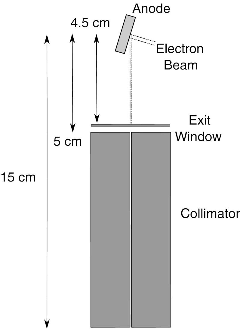
Methods: Monte Carlo calculations were performed using EGSnrc-based codes. The proposed small animal research MRT device design includes carbon nanotube cathodes shaped to match the corresponding MRT collimator apertures, a common reflection anode with filter, and a MRT collimator. Each collimator aperture is sized to deliver a beam width ranging from 30 to 200 μm at 18.6 cm source-to-axis distance. Design parameters studied with Monte Carlo include electron energy, cathode design, anode angle, filtration, and collimator design. Calculations were performed for single and multibeam configurations.

Results: Increasing the energy from 100 kVp to 160 kVp increased the photon fluence through the collimator by a factor of 1.7. Both energies produced a largely uniform fluence along the long dimension of the microbeam, with 5% decreases in intensity near the edges. The isocentric dose rate for 160 kVp was calculated to be 700 Gy∕min∕A in the center of a 3 cm diameter target. Scatter contributions resulting from collimator size were found to produce only small (<7%) changes in the dose rate for field widths greater than 50 μm. Dose vs depth was weakly dependent on filtration material. The peak-to-valley ratio varied from 10 to 100 as the separation between adjacent microbeams varies from 150 to 1000 μm.

Conclusions: Monte Carlo simulations demonstrate that the proposed compact MRT system design is capable of delivering a sufficient dose rate and peak-to-valley ratio for small animal MRT studies.


Figures

Figure 1
Figure 1
Cartoon illustration of the proposed ring-design compact MRT system design. The design can scaled for small animal research and potential human therapy application. (a) Illustration of the basic concept of the compact MRT device in clinical use. The linear circular x-ray microbeam source is located within the circular x-ray tube housing. Power supplies, control electronics, and other supporting components of the MRT device are not shown. (b) A top view schematic of a segmented ring configuration consists of 24 linear segment sources equally spaced within the ring. For better clarity only beams from selected linear source segments are shown, emitting multiple planar microbeams as shown in (c). (c) A single linear segment anode, in which multiple parallel diverging microbeams are produced. The simulation reported in this article included up to 30 parallel planar microbeams.
Figure 2
Figure 2
Geometry of prototype single-direction microbeam MRT component used in Monte Carlo simulations. The 80-μm collimator aperture is not drawn to scale.
Figure 3
Figure 3
Microbeam peak dose rate vs angle for 150-kVp configuration. The single direction microbeam width is 100 μm.
Figure 4
Figure 4
Fluence distribution of photons emerging from MRT collimator for 10° anode angle. (a) The fluence distribution in the narrow dimension for an 80.6-μm wide collimator projecting to a 100-μm wide microbeam at isocenter. (b) The fluence in the long dimension for an 8.1 cm long extended collimator projecting to 10 cm at isocenter. The length of the microbeam can be defined by the length of the collimator aperture.
Figure 5
Figure 5
Microbeam percentage depth dose of the MRT in the cylindrical water target for three different filtration thickness/materials.
Figure 6
Figure 6
Energy spectrum of a 150 kV beam before and after passing through the copper collimator. The narrow peak is a characteristic x-ray peak from the tungsten anode.
Figure 7
Figure 7
Log-linear plot of the dose profile of a 160-kVp microbeam at 1.5 cm depth in a water target. The beam is collimated to form a 100-μm wide beam (FWHM) at 1.5 cm depth.
Figure 8
Figure 8
Dose profile from multiple parallel 160 kV microbeams of 100-μm width at depth of 15 mm. The distribution covers 1 cm with 33 microbeams spaced 300 μm apart.
Figure 9
Figure 9
Peak-to-valley ratio for a single direction microbeam array irradiating a 1 cm tumor at different separation distances between adjacent beams (pitch) as shown in Fig. 8.
Figure 10
Figure 10
Microbeam dose profiles at beam attenuating depths of 5 mm, 15 mm (phantom center), and 25 mm. The microbeam energy is 160 kV and the dose profile is simulated in a mouse phantom of 3 cm diameter.
Figure 11
Figure 11
Microbeam peak dose rate vs collimator (beam) width for the 160 kV single direction microbeam configuration. The dose rate for collimators 100 μm or larger is approximately constant within the statistical uncertainty.
Figure 12
Figure 12
Dose distributions within a microbeam plane for the ring-shaped source MRT design for 12 (left) and 24 (right) microbeam-direction configurations. Each microbeam is conformal in the long dimension of the beam to a 5 mm tumor at the center of a 30 mm diameter cylindrical target. The dose distributions displayed are within the plane of one of the microbeams. Dose profiles perpendicular to the microbeam plane are shown in Fig. 8.

References

    1. Bortfeld T., “IMRT: A review and preview,” Phys. Med. Biol. 51, R363–379 (2006).10.1088/0031-9155/51/13/R21 - DOI - PubMed
    1. Fenwick J. D., Riley S. W., and Scott A. J., “Advances in intensity-modulated radiotherapy delivery,” Cancer Treat Res. 139, 193–214 (2008).10.1007/978-0-387-36744-6_10 - DOI - PubMed
    1. Yu C., Shepard D., Earl M., Cao D., Luan S., Wang C., and Chen D. Z., “New developments in intensity modulated radiation therapy,” Technol. Cancer Res. Treat. 5, 451–464 (2006). - PubMed
    1. Brock K. K., “Image registration in intensity-modulated, image-guided and stereotactic body radiation therapy,” Front Radiat. Ther. Oncol. 40, 94–115 (2007).10.1159/000106030 - DOI - PubMed
    1. Pollack A., Hanlon A., Horwitz E. M., Feinenberg S., Uzzo R. G., and Price R. A., “Radiation therapy dose escalation for prostate cancer: A rationale for IMRT,” World J. Urol. 21, 200–208 (2003).10.1007/s00345-003-0356-x - DOI - PubMed

Publication types

Substances