. 2012 Oct 15;211(1):11-21.
doi: 10.1016/j.jneumeth.2012.08.003. Epub 2012 Aug 14.

Single electrode dynamic clamp with StdpC

Affiliations

Single electrode dynamic clamp with StdpC

David Samu et al. J Neurosci Methods. .

Abstract

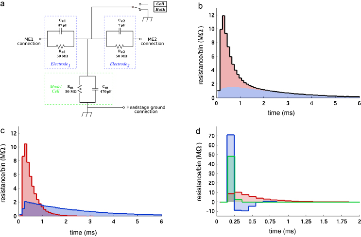
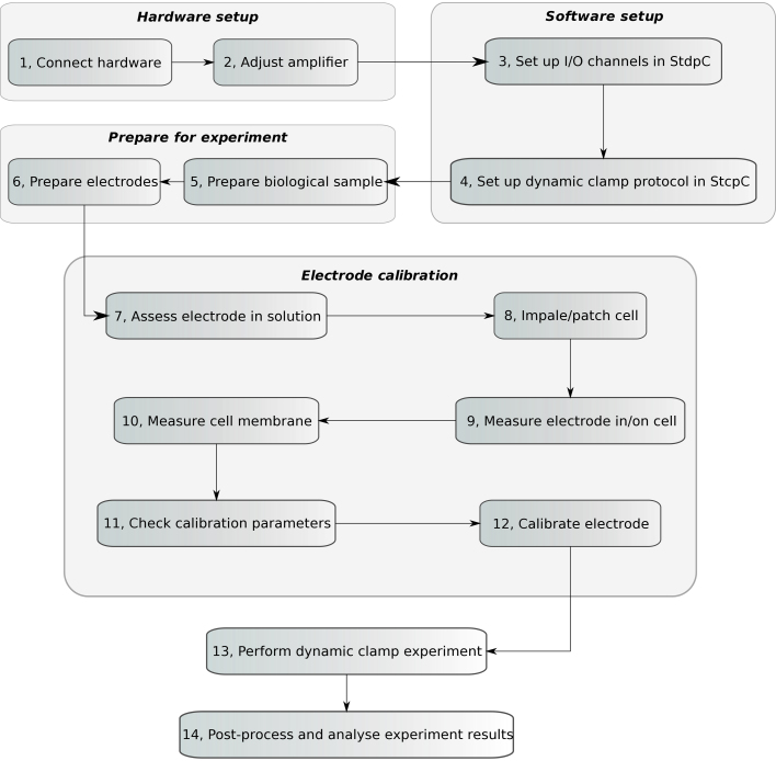
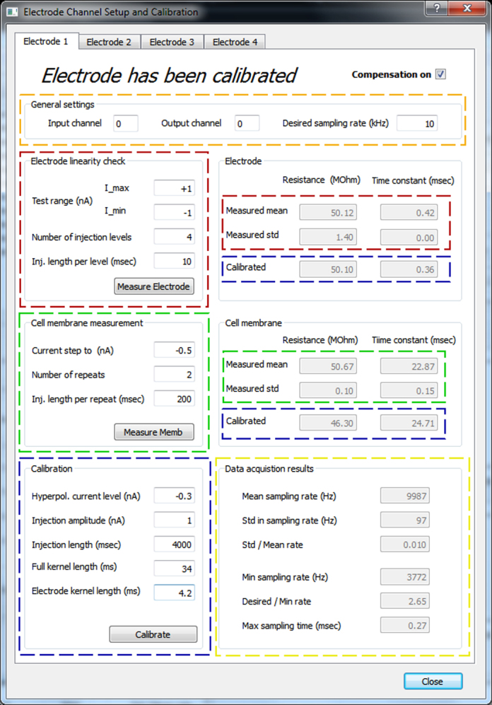
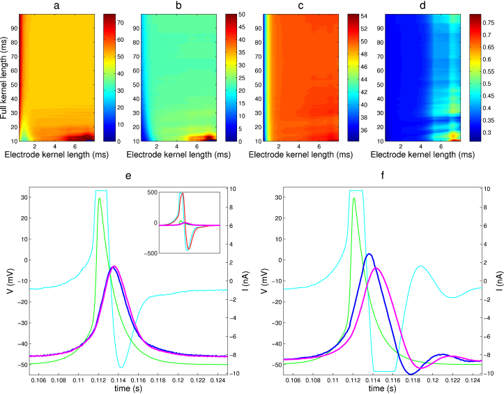
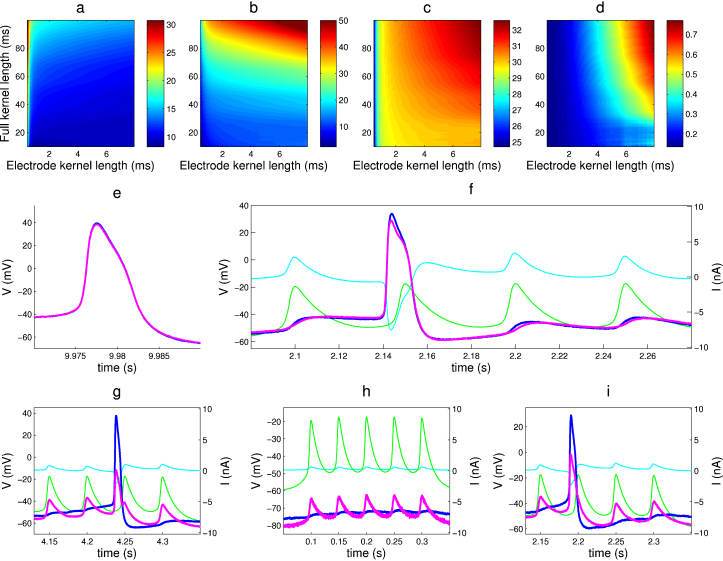
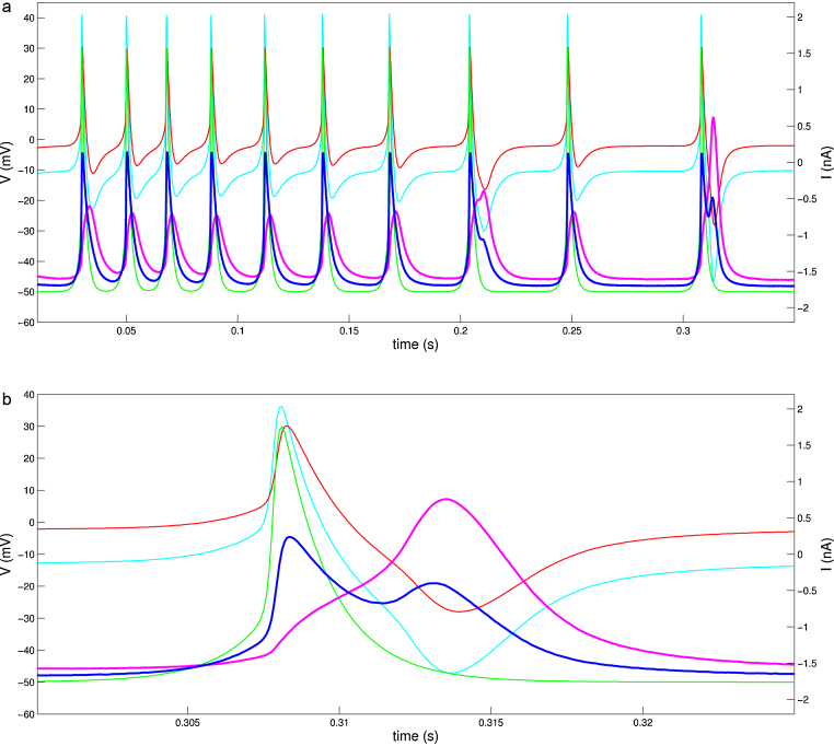
Dynamic clamp is a powerful approach for electrophysiological investigations allowing researchers to introduce artificial electrical components into target neurons to simulate ionic conductances, chemical or electrotonic inputs or connections to other cells. Due to the rapidly changing and potentially large current injections during dynamic clamp, problematic voltage artifacts appear on the electrode used to inject dynamic clamp currents into a target neuron. Dynamic clamp experiments, therefore, typically use two separate electrodes in the same cell, one for recording membrane potential and one for injecting currents. The requirement for two independent electrodes has been a limiting factor for the use of dynamic clamp in applications where dual recordings of this kind are difficult or impossible to achieve. The recent development of an active electrode compensation (AEC) method has overcome some of these prior limitations, permitting artifact-free dynamic clamp experimentation with a single electrode. Here we describe an AEC method for the free dynamic clamp software StdpC. The AEC component of StdpC is the first such system implemented for the use of non-expert users and comes with a set of semi-automated configuration and calibration procedures that facilitate its use. We briefly introduce the AEC method and its implementation in StdpC and then validate it with an electronic model cell and in two different biological preparations.


Figures

Fig. 1
Fig. 1
Illustration of the electrode kernel concept. (a) Electronic circuit (“model cell”) used for the first series of verification experiments. The three RC circuits represent two electrodes and the membrane of a neuron respectively. (b) Estimated full kernel K for the model cell. The colours indicate the contributions from the electrode kernel Ke (red) and the filtered membrane kernel Km * Ke/∫Ke (blue). (c) Electrode kernel Ke (red) and membrane kernel Km (blue) after numerical separation. (d) Effect of capacitance compensation of slow electrodes by the amplifier. Without capacitance compensation (red) the estimated electrode kernel of a slow electrode is too broad, while too much compensation (blue) introduces oscillatory instabilities. The green kernel is estimated at an optimal level of capacitance compensation.
Fig. 2
Fig. 2
Schematic diagram of the general steps of an AEC compensated dynamic clamp experiment using StdpC. The six main parts of the procedure are: hardware setup, software setup, experiment preparation, electrode calibration, performing experiment, and finally, result analysis. A detailed explanation of these steps is given in Sections 3 and 4.
Fig. 3
Fig. 3
Electrode channel setup and calibration panel, showing the parts of the user interface corresponding to the main steps of the electrode calibration procedure. Five main parts are highlighted: gold: electrode setup, red: electrode measurement, both in bath and in/on a cell, green: cell membrane measurement, only after impalement/patching, blue: calibration utilities, yellow: for displaying result on data acquisition timing. Editable text fields on the top and left side of the panel have white background, while the gray shaded fields on the right side are not editable and display information only. Each function on the left side (electrode linearity check, cell membrane measurement, and calibration) can be initiated by its corresponding button, and the obtained results are displayed in the information fields on the right side, highlighted with the same colour. After triggering any of the three processes, the data acquisition results subpanel is updated as well in order to allow the user to assess the stability of the measurement/calibration. (For interpretation of the references to colour in this figure legend, the reader is referred to the web version of the article.)
Fig. 4
Fig. 4
Demonstration of artifact compensation on a model cell. (a–d) AEC estimated circuit properties obtained from electrode calibration for a wide region of AEC's two crucial parameters (full kernel length and electrode kernel length, see Brette et al. (2008) for details). There is a large area in this parameter region where the true resistances and time constants are recovered correctly. (e–f) Comparison of AEC and bridge balance compensation for simulating a 500 nS gap junction (electrical synapse) from a simulated cell (spike generator) to the (physical) model cell. (e) Retrieved membrane potential using AEC and the AEC calculated electrode artifact (inset). (f) Results of using bridge balance compensation. Colour code: green: spike generator potential, cyan: injected current, red: calculated electrode artifact (Ve), magenta: calculated membrane potential (Vraw − Ve) in case of AEC (e), amplifier provided measurement of the membrane potential in case of bridge balance (g), blue: control (“true”) membrane potential on a separate channel. The bridge balance compensated signal is delayed and exhibits artifactual damped oscillations. This is a good example of how the errors in compensation are fed back into the system during dynamic clamp, leading to marked differences in the entire system's behavior. Model cell properties: model electrode: Re = 50 MΩ, τe = 0.35 ms, model membrane: Rm = 50 MΩ, τm = 23 ms.
Fig. 5
Fig. 5
Demonstration of AEC compensation on the Lynmaea stagnalis CGC cell. (a–d) Electrode and (passive) cell membrane properties obtained from the electrode calibration results for a wide region of AEC's two most sensitive parameters (full kernel length and electrode kernel length, see Brette et al. (2008) for details). (e) Spontaneous recorded activity of the cell. (f–i) Compensation results for three investigated electrode artifact compensation techniques, while simulating a symmetric, non-rectifying gap junction synapse between StpdC's spike generator and the CGC: AEC at 100 nS (f), bridge balance at 50 nS (g) and bridge balance and capacitance neutralization combined at 20 nS (h). (i) Example of failed AEC compensation due to a too polarized electrode. Colour code: green: spike generator potential, cyan: injected current, magenta: calculated membrane potential (Vraw − Ve) in case of AEC (f and i), membrane potential as provided by the amplifier in the other cases (e, g and h), blue: control (“true”) membrane potential on an independent electrode and channel.
Fig. 6
Fig. 6
AEC compensation for a patch electrode demonstrated on a cultured rat hippocampal neuron. (a) Repetitive spike generator stimulation of a neuron through a gap junction with 30 nS coupling strength. (b) Last stimulation from a, shown at higher temporal resolution (see time axes). Colour code: green: spike generator potential, cyan: injected current, red: calculated electrode artifact (Ve), magenta: calculated membrane potential (Vraw − Ve), blue: raw voltage as provided by the amplifier (uncompensated membrane potential).

References

    1. Alle H., Geiger J.R.P. Combined analog and action potential coding in hippocampal mossy fibers. Science. 2006;311(5765):1290–1293. - PubMed
    1. Bettencourt J.C., Lillis K.P., Stupin L.R., White J.A. Effects of imperfect dynamic clamp: computational and experimental results. J Neurosci Methods. 2008;169(2):282–289. - PMC - PubMed
    1. Brette R., Piwkowska Z., Monier C., Rudolph-Lilith M., Fournier J., Levy M., Frgnac Y., Bal T., Destexhe A. High-resolution intracellular recordings using a real-time computational model of the electrode. Neuron. 2008;59(3):379–391. - PubMed
    1. Brette R., Piwkowska Z., Rudolph M., Bal T., Destexhe A. A non-parametric electrode model for intracellular recording. Neurocomputing. 2007;70(10–12):1597–1601.
    1. Butera R., Jr., Wilson C.G., Delnegro C.A., Smith J.C. A methodology for achieving high-speed rates for artificial conductance injection in electrically excitable biological cells. IEEE Trans Biomed Eng. 2001;48(12):1460–1470. - PubMed

Publication types

LinkOut - more resources