

doi: 10.4302/plp.2011.4.02.
Imaging limbal and scleral vasculature using Swept Source Optical Coherence Tomography
Affiliations
- PMID: 22919461
- PMCID: PMC3423982
- DOI: 10.4302/plp.2011.4.02
Item in Clipboard
Imaging limbal and scleral vasculature using Swept Source Optical Coherence Tomography
Photonics Lett Pol.
.
Abstract
We demonstrate an application of high-speed swept source optical coherence tomography for vessel visualization in the anterior segment of the human eye. The human corneo-scleral junction and sclera was imaged in vivo. Imaging was performed using a swept source OCT system operating at the 1050nm wavelength range and 100kHz A-scan rate. High imaging speed enables the generation of 3D depth-resolved vasculature maps. The vessel visualization method revealed a rich vascular system in the conjunctiva and episclera.
Figures
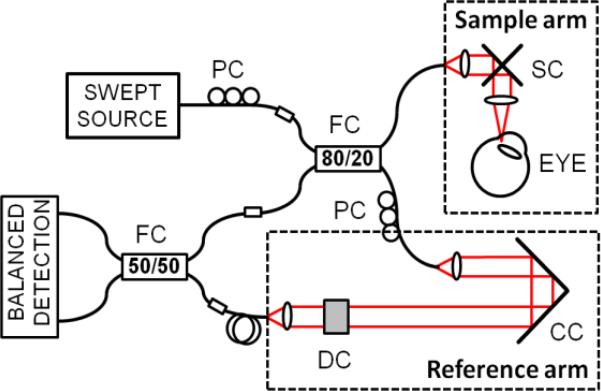
Swept source OCT system. PC – polarization controller, FC – fiber coupler, SC – galvanometric scanners, CC – corner cube, DC – dispersion compensation.
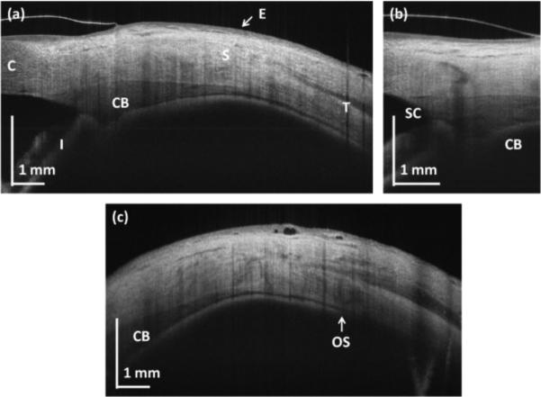
OCT cross-sections of the human corneo-scleral region. (a) Structural high-definition scan (protocol A); (b) limbus (protocol B); (c) peripheral sclera (protocol A). C – cornea, S – sclera, E – epithelium, I – iris, SC – Schlemm's canal, OS – ora serrata.
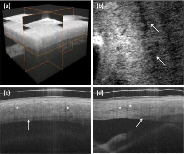
In vivo 3-D imaging of human limbus. (a) rendering and 3-D reconstruction of data set. (b) C-scan (x-y cross section). Arrows show Schlemm's canal. (c) B-scan in fast scanning axis (y-z cross-section). (d) B-scan in slow scanning axis (x-z cross section). Protocol C from Table 1 was used for scanning the eye. Asterisks show blood vessel shadows.
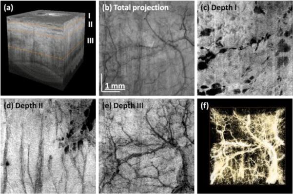
Three-dimensional reconstruction of human limbus after flattening (a). En face projection of structural images (b). Virtual C-scans (projections) from angiographic data set showing vascular networks in episclera (c) and deeper sclera (d)-(e). Vasculature rendering after thresholding and colorscale inversion (f). Data set was acquired using protocol D.
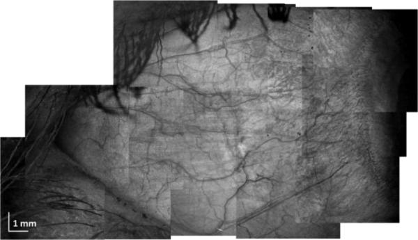
Large area scleral OCT imaging. Composite projection image from 12 individual data sets acquired using protocol D.
Similar articles
-
In vivo volumetric depth-resolved vasculature imaging of human limbus and sclera with 1μm swept source phase-variance optical coherence angiography.J Opt. 2015 Jun;17(6):065301. doi: 10.1088/2040-8978/17/6/065301. J Opt. 2015. PMID: 25984290 Free PMC article.
-
Morphological features in anterior scleral inflammation using swept-source optical coherence tomography with multiple B-scan averaging.Br J Ophthalmol. 2017 Apr;101(4):411-417. doi: 10.1136/bjophthalmol-2016-308561. Epub 2016 Jul 7. Br J Ophthalmol. 2017. PMID: 27388252
-
Imaging the posterior segment of the eye using swept-source optical coherence tomography in myopic glaucoma eyes: comparison with enhanced-depth imaging.Am J Ophthalmol. 2014 Mar;157(3):550-7. doi: 10.1016/j.ajo.2013.11.008. Epub 2013 Nov 12. Am J Ophthalmol. 2014. PMID: 24239773
-
Advances in swept-source optical coherence tomography and optical coherence tomography angiography.Adv Ophthalmol Pract Res. 2022 Nov 25;3(2):67-79. doi: 10.1016/j.aopr.2022.10.005. eCollection 2023 May-Jun. Adv Ophthalmol Pract Res. 2022. PMID: 37846376 Free PMC article. Review.
-
Clinical utility of anterior segment swept-source optical coherence tomography in glaucoma.Oman J Ophthalmol. 2016 Jan-Apr;9(1):3-10. doi: 10.4103/0974-620X.176093. Oman J Ophthalmol. 2016. PMID: 27013821 Free PMC article. Review.
Cited by
-
High resolution anterior segment optical coherence tomography of ocular surface lesions: A review and handbook.Expert Rev Ophthalmol. 2021;16(2):81-95. doi: 10.1080/17469899.2021.1851598. Epub 2020 Dec 28. Expert Rev Ophthalmol. 2021. PMID: 36313187 Free PMC article.
-
Comparison of anterior segment optical coherence tomography findings in acanthamoeba keratitis and herpetic epithelial keratitis.Int J Ophthalmol. 2018 Aug 18;11(8):1416-1420. doi: 10.18240/ijo.2018.08.26. eCollection 2018. Int J Ophthalmol. 2018. PMID: 30140650 Free PMC article.
-
Ultrahigh-resolution OCT imaging of the human cornea.Biomed Opt Express. 2017 Jan 30;8(2):1221-1239. doi: 10.1364/BOE.8.001221. eCollection 2017 Feb 1. Biomed Opt Express. 2017. PMID: 28271013 Free PMC article.
-
Full circumferential morphological analysis of Schlemm's canal in human eyes using megahertz swept source OCT.Biomed Opt Express. 2021 Jun 7;12(7):3865-3877. doi: 10.1364/BOE.426218. eCollection 2021 Jul 1. Biomed Opt Express. 2021. PMID: 34457385 Free PMC article.
-
Relationship between vessel diameter and depth measurements within the limbus using ultra-high resolution optical coherence tomography.J Optom. 2018 Jan-Mar;11(1):57-65. doi: 10.1016/j.optom.2017.02.003. Epub 2017 Jun 17. J Optom. 2018. PMID: 28629902 Free PMC article.
References
-
- Drexler W, Fujimoto JG, editors. Optical Coherence Tomography. Technology and Applications. Springer; Berlin-Heidelberg: 2008.
-
- Zysk AM, Oldenburg AL, Marks DL, Nguyen FT, Boppart SA. J. Biomed. Opt. 2007;12:051403. - PubMed
Grants and funding
LinkOut - more resources
Full Text Sources
Other Literature Sources