Review
. 2012 Nov;64(14):1628-38.
doi: 10.1016/j.addr.2012.08.006. Epub 2012 Aug 19.

MEMS-enabled implantable drug infusion pumps for laboratory animal research, preclinical, and clinical applications

Affiliations
Review

MEMS-enabled implantable drug infusion pumps for laboratory animal research, preclinical, and clinical applications

Ellis Meng et al. Adv Drug Deliv Rev. 2012 Nov.

Abstract

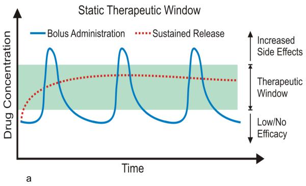
Innovation in implantable drug delivery devices is needed for novel pharmaceutical compounds such as certain biologics, gene therapy, and other small molecules that are not suitable for administration by oral, topical, or intravenous routes. This invasive dosing scheme seeks to directly bypass physiological barriers presented by the human body, release the appropriate drug amount at the site of treatment, and maintain the drug bioavailability for the required duration of administration to achieve drug efficacy. Advances in microtechnologies have led to novel MEMS-enabled implantable drug infusion pumps with unique performance and feature sets. In vivo demonstration of micropumps for laboratory animal research and preclinical studies include acute rapid radiolabeling, short-term delivery of nanomedicine for cancer treatment, and chronic ocular drug dosing. Investigation of MEMS actuators, valves, and other microstructures for on-demand dosing control may enable next generation implantable pumps with high performance within a miniaturized form factor for clinical applications.


Figures

Figure 1
Figure 1
Illustrations depicting (a) static therapeutic window and (b) dynamic therapeutic window.
Figure 1
Figure 1
Illustrations depicting (a) static therapeutic window and (b) dynamic therapeutic window.
Figure 2
Figure 2
Photograph of two electrothermal valve designs. The top row shows the valve layout. The middle row shows a close-up photograph of the valve element which is situated across the lumen catheter and thus the flow path. The bottom row shows the opened valve following the application of current. The left column optical micrographs originally appeared in [23] © 2009 IEEE. Reprinted, with permission, from IEEE/ASME Journal of Microelectromechanical Systems. The top and middle optical micrographs in the right column originally appeared in [24] – Reproduced by permission of The Royal Society of Chemistry.
Figure 3
Figure 3
Photographs showing the individual components required for valve assembly (left) and a completely assembled valve packaged using catheter segments (right). Briefly, double-sided pressure sensitive adhesive rings are used to secure the valve to the catheter segments. Conductive epoxy is used to connect wires to the valve’s electrical contact pads and finally, the entire assembly is stabilized with a bead of epoxy [24] – Reproduced by permission of The Royal Society of Chemistry.
Figure 4
Figure 4
Photograph of the microbolus infusion pump with integrated MEMS electrothermal valve [23] © 2009 IEEE. Reprinted, with permission, from IEEE/ASME Journal of Microelectromechanical Systems.
Figure 5
Figure 5
Three dimensional concept drawing of a MEMS electrolysis-based drug delivery infusion pump showing the major parts and components. The top illustraton shows a view of the entire pump. The bottom view is a cut-away that reveals the structure of the pump actuator including the bellows and interdigitated electrolysis electrodes.
Figure 6
Figure 6
Cross-sectional illustrations showing (a) the structure of the pump and (b) electrolysis pumping principle. Gas generation due to electrolysis deflects the flexible bellows. The increase in pressure acts on the in-line check valve and forces drug through the catheter outlet. After the pump is turned off, the gases recombine into water. When the drug reservoir is empty, the pump is refilled using a non-coring syringe needle through the drug refill port in a manner that does not interfere with the bellows actuator as indicated by the dashed line.
Figure 7
Figure 7
Representative data showing the performance range of the electrolysis pump using Pt/Ti interdigitated electrodes patterned on soda lime substrate. Current-controlled pumping of water using different Parylene bellows configurations for high flow rate pumping (>10 μL/min) is shown. A wide range of flow rates (pL/min to μL/min) can be generated simply by controlling the magnitude of the applied current (μA to mA) [72] © 2011 IEEE. Reprinted, with permission, from Proceedings of the 16th International Solid-State Sensors, Actuators and Microsystems Conference (TRANSDUCERS).
Figure 8
Figure 8
Photograph of a MEMS electrolysis-based drug delivery infusion pump for timolol administration in rabbit models of glaucoma.

References

    1. Bruguerolle B, Labrecque G. Rhythmic pattern in pain and their chronotherapy. Adv Drug Deliv Rev. 2007;59:883–895. - PubMed
    1. Urquhart J. INTERNAL MEDICINE IN THE 21ST CENTURY: Controlled drug delivery: therapeutic and pharmacological aspects. J Intern Med. 2000;248:357–376. - PubMed
    1. Dash AK, Cudworth GC., 2nd Therapeutic applications of implantable drug delivery systems. J Pharmacol Toxicol Methods. 1998;40:1–12. - PubMed
    1. Ranade VV, Hollinger MA. Drug delivery systems. 2nd ed CRC Press; Boca Raton: 2004.
    1. Sefton MV. Implantable Pumps in Medical Applications of Controlled Release. In: Langer RS, Wise DL, editors. Medical applications of controlled release. CRC Press; Boca Raton, Fla.: 1984. pp. 129–158.

Publication types