. 2012 Aug 24:6:56.
doi: 10.3389/fncom.2012.00056. eCollection 2012.

Invariant object recognition based on extended fragments

Affiliations

Invariant object recognition based on extended fragments

Evgeniy Bart et al. Front Comput Neurosci. .

Abstract

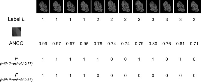
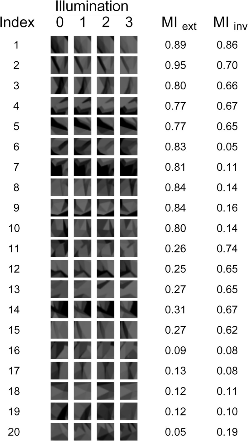
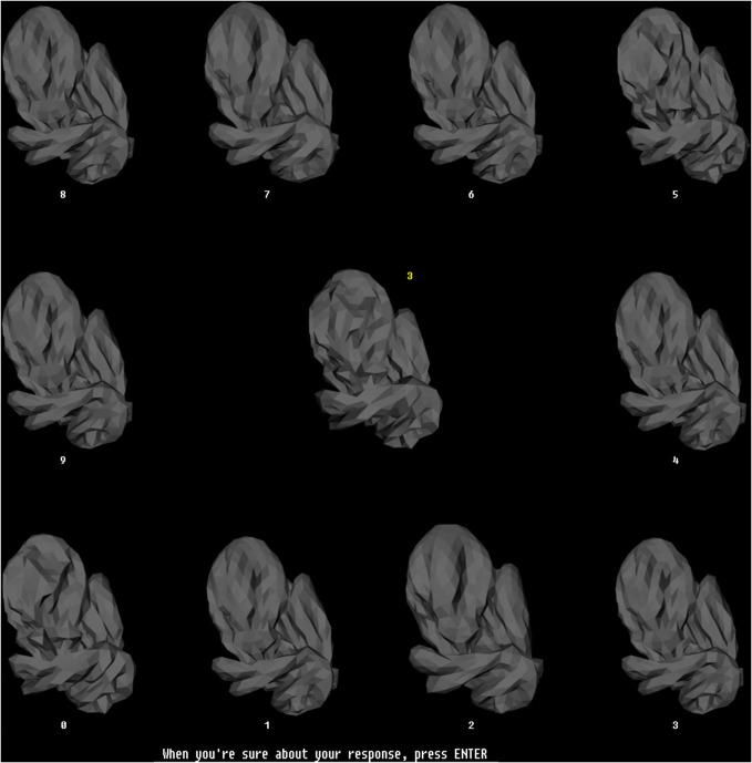
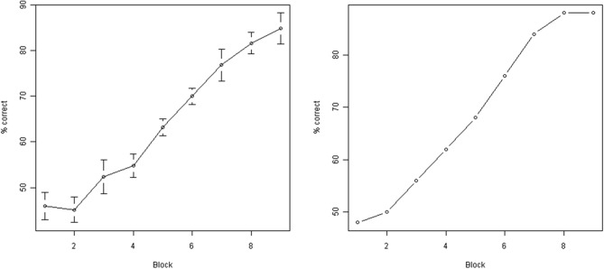
Visual appearance of natural objects is profoundly affected by viewing conditions such as viewpoint and illumination. Human subjects can nevertheless compensate well for variations in these viewing conditions. The strategies that the visual system uses to accomplish this are largely unclear. Previous computational studies have suggested that in principle, certain types of object fragments (rather than whole objects) can be used for invariant recognition. However, whether the human visual system is actually capable of using this strategy remains unknown. Here, we show that human observers can achieve illumination invariance by using object fragments that carry the relevant information. To determine this, we have used novel, but naturalistic, 3-D visual objects called "digital embryos." Using novel instances of whole embryos, not fragments, we trained subjects to recognize individual embryos across illuminations. We then tested the illumination-invariant object recognition performance of subjects using fragments. We found that the performance was strongly correlated with the mutual information (MI) of the fragments, provided that MI value took variations in illumination into consideration. This correlation was not attributable to any systematic differences in task difficulty between different fragments. These results reveal two important principles of invariant object recognition. First, the subjects can achieve invariance at least in part by compensating for the changes in the appearance of small local features, rather than of whole objects. Second, the subjects do not always rely on generic or pre-existing invariance of features (i.e., features whose appearance remains largely unchanged by variations in illumination), and are capable of using learning to compensate for appearance changes when necessary. These psychophysical results closely fit the predictions of earlier computational studies of fragment-based invariant object recognition.

Keywords: form vision; illumination constancy; informative fragments; invariant recognition; mutual information.


Figures

Figure 1
Figure 1
Training stimuli. (A) Five example digital embryos from our training set. All five embryos are shown under the same illumination. Note that the embryos are perceptually similar enough that distinguishing among them is not trivial. (B) The four directions of illumination used in our experiments. The directions are denoted by arbitrary numbers: 0 (illuminated from bottom left), 1 (from top right), 2 (from top left), and 3 (from bottom right). The same digital embryo is shown under the four illumination directions to illustrate the appearance changes induced by changes in illumination.
Figure 2
Figure 2
An example of MI computation. The top row shows images of three different objects (labeled 1, 2, and 3), with four different images for each object. The second row shows the object labels. The MI of the fragment shown (enlarged) in row three was computed. The fourth row shows the ANCC values for this fragment in each image. Using a threshold value of 0.77 gives the presence/absence values of the F variable shown in the fifth row. Since there are four 0's in this example, out of 12 total observations, we get an empirical estimate p(F = 0) = 4/12 = 1/3. Similarly, the following estimates can be obtained: p(F = 1) = 2/3; p(L = 1) = 1/3; p(L = 2) = 1/3; p(L = 3) = 1/3; p(F = 0, L = 1) = 0; p(F = 0, L = 2) = 1/6; p(F = 0, L = 3) = 1/6; p(F = 1, L = 1) = 1/3; p(F = 1, L = 2) = 1/6; p(F = 1, L = 3) = 1/6. Substituting these values into Equation (1), we get MI = 0.25. The ANCC values need to be computed only once, but the F values need to be recomputed for every threshold. For example, for the threshold setting of 0.87, the F values in row six are obtained, giving MI = 0.92. If the ANCC values are sorted in increasing order, the following sequence is obtained: 0.71, 0.74, 0.74, 0.76, 0.78, 0.79, 0.80, 0.81, 0.95, 0.97, 0.97, 0.99. Any threshold in-between two consecutive ANCC values will result in the same F values and therefore in the same MI. Therefore, in this example only 11 representative threshold values need to be evaluated to select the optimal threshold.
Figure 3
Figure 3
The 20 fragments used in our experiments. The appearance of each fragment under each of the four illuminations is shown, as well as the corresponding Extended and Invariant MI values (MIext and MIinv, respectively).
Figure 4
Figure 4
The training paradigm. This figure illustrates the configuration of stimuli during a typical trial during the training phase. During each trial, a randomly selected sample embryo was shown in the center in a randomly selected illumination. The 10 test stimuli were shown simultaneously arrayed along the periphery of the screen. The illumination was the same across all sample stimuli, but was different from the illumination of the sample embryo. The test embryos were assigned randomly to numbered locations (white numbers). One of the test embryos was the same object as the sample embryo, but at a different illumination. The subjects had to identify the test embryo that matched the sample embryo, and enter the number of this test embryo using the computer's keyboard, which then appeared as a yellow number next to the sample embryo. Note that this task required the subjects to generalize across the illuminations. The subjects pressed another key to finalize their response. After the subjects finalized their response, they received visual feedback (not shown), along with the correct response, if the subject's response was incorrect. Subjects had unlimited time both to perform the task and to examine the subsequent feedback. The stimulus configuration shown subtended 26° × 26° during the actual experiments.
Figure 5
Figure 5
Subject performance during training. Y axis: % correct responses during a single block (50 individual trials). X axis: block number. Left: average across all subjects (error bars indicate standard error of the mean). Right: performance of a single representative subject (subject M00). As can be seen, the performance improved significantly as a result of training.
Figure 6
Figure 6
The testing paradigm. A composite object (center) and two test objects (left and right) were presented simultaneously during each trial. The composite object was occluded by a translucent surface with a hole, such that only the given object fragment was visible, unoccluded, through the hole, and the location of the fragment relative to the overall object was apparent through the translucent occluder. Subjects were informed that only the fragment, but not the darkened remainder of the composite object, was useful for the task. The fragment in the composite object was always in illumination 0, and both test embryos were always at illumination 3. The fragment was present in one of the test embryos, and absent from the other (“positive” and “negative” embryos, respectively). The location of the two test embryos was shuffled randomly from one trial to the next. Subjects had to report, using a key press, whether the positive test embryo was to the left or right of the composite object.
Figure 7
Figure 7
The 20 fragments selected by the G1 measure. The appearance of each fragment under each of the four illuminations is shown, as well as the fragment's Extended and Invariant MI.
Figure 8
Figure 8
Scatter plots of performance (Y axis) with the five predictor variables (X axis) defined in the “Results” section. Hexagonal binning was used due to a large number of overlapping points. The depth of shading of each bin indicates the number of points that fall in it, according to the legend at the bottom right.
Figure 9
Figure 9
Scatter plot of performance (Y axis) with the M03 variable (X axis) defined in the “Results” section. Hexagonal binning was used due to a large number of overlapping points. The depth of shading of each bin indicates the number of points that fall in it, according to the legend on the right. The red line indicates the “visual recognizability” threshold, defined in the “Results” section. Note that testing configurations remained discernible even below this threshold (blue rectangle). However, subjects systematically underperformed in some highly recognizable configurations (green rectangle), indicating that factors other than visual recognizability affected performance. See text for details.

Similar articles

Cited by

References

    1. Bart E., Byvatov E., Ullman S. (2004). View-invariant recognition using corresponding object fragments, in Proceedings ECCV, Part II, (New York, NY: Springer-Verlag; ), 152–165
    1. Biederman I., Cooper E. E. (2009). Translational and reflectional priming invariance: a retrospective. Perception 38, 809–817 - PubMed
    1. Brady M. J., Kersten D. (2003). Bootstrapped learning of novel objects. J. Vis. 3, 413–422 - PubMed
    1. Bukach C. M., Gauthier I., Tarr M. J. (2006). Beyond faces and modularity: the power of an expertise framework. Trends Cogn. Sci. 10, 159–166 10.1016/j.tics.2006.02.004 - DOI - PubMed
    1. Christou C., Bulthoff H. H. (2000). Perception, representation and recognition: a holistic view of recognition. Spat. Vis. 13, 265–275 10.1163/156856800741081 - DOI - PubMed

LinkOut - more resources