Review
. 2012 Oct;30(10):546-54.
doi: 10.1016/j.tibtech.2012.07.005. Epub 2012 Aug 30.

Recent advances in bone tissue engineering scaffolds

Affiliations
Review

Recent advances in bone tissue engineering scaffolds

Susmita Bose et al. Trends Biotechnol. 2012 Oct.

Abstract

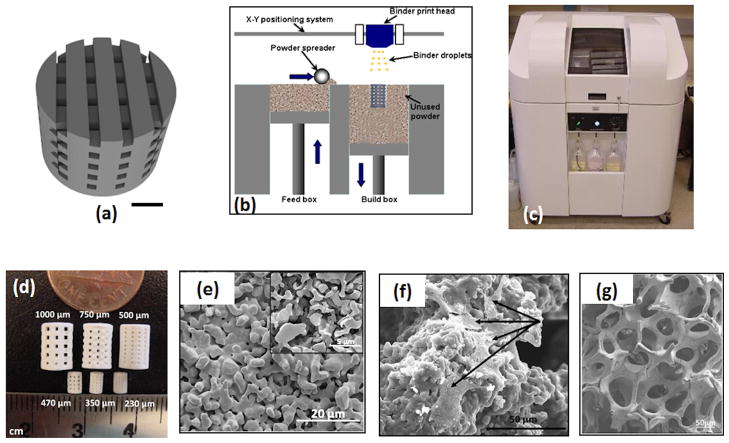
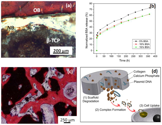
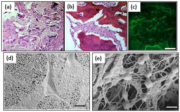
Bone disorders are of significant concern due to increase in the median age of our population. Traditionally, bone grafts have been used to restore damaged bone. Synthetic biomaterials are now being used as bone graft substitutes. These biomaterials were initially selected for structural restoration based on their biomechanical properties. Later scaffolds were engineered to be bioactive or bioresorbable to enhance tissue growth. Now scaffolds are designed to induce bone formation and vascularization. These scaffolds are often porous, made of biodegradable materials that harbor different growth factors, drugs, genes, or stem cells. In this review, we highlight recent advances in bone scaffolds and discuss aspects that still need to be improved.


Figures

Figure 1
Figure 1
(a) CAD image of a porous scaffold. Square channels are oriented at 0°/90° for succeeding layers. The scale bar represents 1cm [33]. (b) Schematic drawing of the SFF 3D printing process. In this process, a printer head sprays the binder on the loose powder bed according to a specific CAD file. A layer of powder is then laid over the binder with a metallic rod followed by binder drying. The process is repeated number of times to build the desired part. (c) The ExOne (Ex One Company, Irwin, PA) 3D printer to create interconnected porous 3D ceramic objects. (d) Digital photograph showing 3D printed TCP scaffolds after sintering. The larger samples are for mechanical characterization and small samples for in vivo testing [34]. (e) Surface morphology of 3D printed TCP scaffolds after microwave sintering at 1250 °C showing a porous scaffold strand. Inset scanning electron micrograph images shows the presence of microporosity in the scaffold [34]. (f) Micrographs of hFOB cells showing the cell morphology and adhesion behavior inside the macropores of 3D printed Si/Zn doped TCP scaffolds after 7 days of culture. Osteoblast cells are indicated by arrow [33]. (g) SEM morphologies of the TCP scaffolds coated with 2.5% PCL w/v in dichloromethane prepared by lost mold method shows the interconnected porosity [54].
Figure 2
Figure 2
(a) Photomicrograph of the 3D printed TCP scaffolds of 350 μm pore size showing development of new bone formation after 2 weeks implantation in the rat femur. Modified Masson’s Goldner trichrome staining of a transverse section: OB: old bone; NB: new bone; MC: mesenchymal cell; NB: osteoid-like new bone [34]. (b) BSA release pro le from a PCL-coated TCP scaffolds. It is evident that the presence of PCL helped in achieving a sustained release of BSA [54]. (c) Micrographs showing bone formation and scaffold degradation of a TCP scaffold loaded with BMSCs [62]. (d) Schematic representation showing degradation behavior and delivery of VEGF from a CaP/collagen scaffold without a non-viral vector. The concept is that the degradation of scaffold will release the plasmid DNA along with CaP. Both CaP and DNA will form a complex that can be up taken by targeted cell and express VEGF and lead to angiogenesis [72].
Figure 3
Figure 3
(a) and (b) represents photomicrograph of 12 weeks post-operative histological samples of nano-hydroxyapatite/collagen/poly (L-lactic acid) and nano-hydroxyapatite/collagen/poly (L-lactic acid)/BMP-2, respectively. BMP-2 loading results in larger area of new bone formation (dark red regions) (magnification: ×200) [24]. (c) Visualization of blood vessel formation in effect of VEGF added BCP ceramics implanted into the cranial window for 2 days, using a vertical illumination fluorescence microscope. Plasma marker fluorescein-isothiocyanate-labeled (FITC) dextran was used to study the microcirculation. Scale bars represent 1mm [30]. Cellular interactions with (d) HA and (e) HA-collagen scaffolds indicate the differences between cellular adhesion behaviors. Bars: 500 nm. The cells anchored on the collagen nanofibers in HA-collagen scaffold [77].

References

    1. Olszta MJ, et al. Bone structure and formation: A new perspective. Materials Science and Engineering: R: Reports. 2007;58:77–116.
    1. Bose S, et al. Processing of controlled porosity ceramic structures via fused deposition. Scripta Materialia. 1999;41:1009–1014.
    1. Darsell J, et al. From CT Scan to Ceramic Bone Graft. Journal of the American Ceramic Society. 2003;86:1076–1080.
    1. Hutmacher DW, et al. Scaffold-based tissue engineering: rationale for computer-aided design and solid free-form fabrication systems. Trends in Biotechnology. 2004;22:354–362. - PubMed
    1. Balla VK, et al. Porous tantalum structures for bone implants: Fabrication, mechanical and in vitro biological properties. Acta Biomaterialia. 2010;6:3349–3359. - PMC - PubMed

Publication types