

Multi-ion distributions in the cytoplasmic domain of inward rectifier potassium channels
- PMID: 22947859
- PMCID: PMC3414900
- DOI: 10.1016/j.bpj.2012.06.023
Multi-ion distributions in the cytoplasmic domain of inward rectifier potassium channels
Abstract
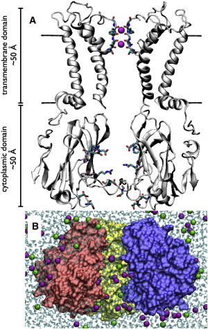
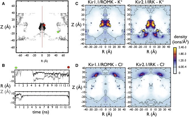
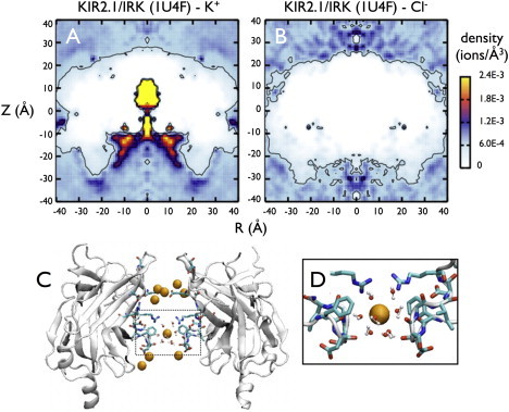
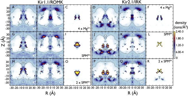
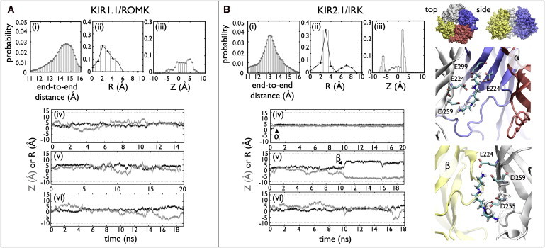
Inward rectifier potassium (Kir) channels act as cellular diodes, allowing unrestricted flow of potassium (K(+)) into the cell while preventing currents of large magnitude in the outward direction. The rectification mechanism by which this occurs involves a coupling between K(+) and intracellular blockers-magnesium (Mg(2+)) or polyamines-that simultaneously occupy the permeation pathway. In addition to the transmembrane pore, Kirs possess a large cytoplasmic domain (CD) that provides a favorable electronegative environment for cations. Electrophysiological experiments have shown that the CD is a key regulator of both conductance and rectification. In this study, we calculate and compare averaged equilibrium probability densities of K(+) and Cl(-) in open-pore models of the CDs of a weak (Kir1.1-ROMK) and a strong (Kir2.1-IRK) rectifier through explicit-solvent molecular-dynamics simulations in ~1 M KCl. The CD of both channels concentrates K(+) ions greater than threefold inside the cytoplasmic pore while IRK shows an additional K(+) accumulation region near the cytoplasmic entrance. Simulations carried out with Mg(2+) or spermine (SPM(4+)) show that these ions interact with pore-lining residues, shielding the surface charge and reducing K(+) in both channels. The results also show that SPM(4+) behaves differently inside these two channels. Although SPM(4+) remains inside the CD of ROMK, it diffuses around the entire volume of the pore. In contrast, this polyatomic cation finds long-lived conformational states inside the IRK pore, interacting with residues E224, D259, and E299. The strong rectifier CD is also capable of sequestering an additional SPM(4+) at the cytoplasmic entrance near a cluster of negative residues D249, D274, E275, and D276. Although understanding the actual mechanism of rectification blockade will require high-resolution structural information of the blocked state, these simulations provide insight into how sequence variation in the CD can affect the multi-ion distributions that underlie the mechanisms of conduction, rectification affinity, and kinetics.
Copyright © 2012 Biophysical Society. Published by Elsevier Inc. All rights reserved.
Figures
Similar articles
-
Functional roles of charged amino acid residues on the wall of the cytoplasmic pore of Kir2.1.J Gen Physiol. 2006 Apr;127(4):401-19. doi: 10.1085/jgp.200509434. Epub 2006 Mar 13. J Gen Physiol. 2006. PMID: 16533896 Free PMC article.
-
The bundle crossing region is responsible for the inwardly rectifying internal spermine block of the Kir2.1 channel.Pflugers Arch. 2014 Feb;466(2):275-93. doi: 10.1007/s00424-013-1322-0. Epub 2013 Jul 20. Pflugers Arch. 2014. PMID: 23873351
-
Inward rectification by polyamines in mouse Kir2.1 channels: synergy between blocking components.J Physiol. 2003 Jul 1;550(Pt 1):67-82. doi: 10.1113/jphysiol.2003.043117. Epub 2003 May 9. J Physiol. 2003. PMID: 12740427 Free PMC article.
-
Mechanism of rectification in inward-rectifier K+ channels.Annu Rev Physiol. 2004;66:103-29. doi: 10.1146/annurev.physiol.66.032102.150822. Annu Rev Physiol. 2004. PMID: 14977398 Review.
-
Polyamines as gating molecules of inward-rectifier K+ channels.Eur J Biochem. 2000 Oct;267(19):5824-9. doi: 10.1046/j.1432-1327.2000.01669.x. Eur J Biochem. 2000. PMID: 10998040 Review.
Cited by
-
Using models to design new bioinspired materials.Biophys J. 2012 Nov 7;103(9):1814-5. doi: 10.1016/j.bpj.2012.09.029. Biophys J. 2012. PMID: 23199906 Free PMC article. No abstract available.
-
Channel rectification made simple.Biophys J. 2025 Feb 18;124(4):587-589. doi: 10.1016/j.bpj.2025.01.013. Epub 2025 Jan 24. Biophys J. 2025. PMID: 39863926 No abstract available.
-
CHARMM at 45: Enhancements in Accessibility, Functionality, and Speed.J Phys Chem B. 2024 Oct 17;128(41):9976-10042. doi: 10.1021/acs.jpcb.4c04100. Epub 2024 Sep 20. J Phys Chem B. 2024. PMID: 39303207 Free PMC article. Review.
-
Vascular inward rectifier K+ channels as external K+ sensors in the control of cerebral blood flow.Microcirculation. 2015 Apr;22(3):183-96. doi: 10.1111/micc.12190. Microcirculation. 2015. PMID: 25641345 Free PMC article. Review.
-
Multi-ion versus single-ion conduction mechanisms can yield current rectification in biological ion channels.J Biol Phys. 2014 Mar;40(2):109-19. doi: 10.1007/s10867-013-9338-4. Epub 2014 Jan 26. J Biol Phys. 2014. PMID: 24463792 Free PMC article.
References
-
- Matsuda H., Saigusa A., Irisawa H. Ohmic conductance through the inwardly rectifying K channel and blocking by internal Mg2+ Nature. 1987;325:156–159. - PubMed
-
- Lopatin A.N., Makhina E.N., Nichols C.G. Potassium channel block by cytoplasmic polyamines as the mechanism of intrinsic rectification. Nature. 1994;372:366–369. - PubMed
-
- Ficker E., Taglialatela M., Brown A.M. Spermine and spermidine as gating molecules for inward rectifier K+ channels. Science. 1994;266:1068–1072. - PubMed
-
- Kuo A., Gulbis J.M., Doyle D.A. Crystal structure of the potassium channel KirBac1.1 in the closed state. Science. 2003;300:1922–1926. - PubMed
Publication types
MeSH terms
Substances
Grants and funding
LinkOut - more resources
Full Text Sources
