Hierarchical super-structure identified by polarized light microscopy, electron microscopy and nanoindentation: Implications for the limits of biological control over the growth mode of abalone sea shells
- PMID: 22967319
- PMCID: PMC3507795
- DOI: 10.1186/2046-1682-5-19
Hierarchical super-structure identified by polarized light microscopy, electron microscopy and nanoindentation: Implications for the limits of biological control over the growth mode of abalone sea shells
Abstract
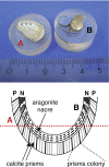
Background: Mollusc shells are commonly investigated using high-resolution imaging techniques based on cryo-fixation. Less detailed information is available regarding the light-optical properties. Sea shells of Haliotis pulcherina were embedded for polishing in defined orientations in order to investigate the interface between prismatic calcite and nacreous aragonite by standard materialographic methods. A polished thin section of the interface was prepared with a defined thickness of 60 μm for quantitative birefringence analysis using polarized light and LC-PolScope microscopy. Scanning electron microscopy images were obtained for comparison. In order to study structural-mechanical relationships, nanoindentation experiments were performed.
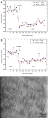
Results: Incident light microscopy revealed a super-structure in semi-transparent regions of the polished cross-section under a defined angle. This super-structure is not visible in transmitted birefringence analysis due to the blurred polarization of small nacre platelets and numerous organic interfaces. The relative orientation and homogeneity of calcite prisms was directly identified, some of them with their optical axes exactly normal to the imaging plane. Co-oriented "prism colonies" were identified by polarized light analyses. The nacreous super-structure was also visualized by secondary electron imaging under defined angles. The domains of the super-structure were interpreted to consist of crystallographically aligned platelet stacks. Nanoindentation experiments showed that mechanical properties changed with the same periodicity as the domain size.
Conclusions: In this study, we have demonstrated that insights into the growth mechanisms of nacre can be obtained by conventional light-optical methods. For example, we observed super-structures formed by co-oriented nacre platelets as previously identified using X-ray Photo-electron Emission Microscopy (X-PEEM) [Gilbert et al., Journal of the American Chemical Society 2008, 130:17519-17527]. Polarized optical microscopy revealed unprecedented super-structures in the calcitic shell part. This bears, in principle, the potential for in vivo studies, which might be useful for investigating the growth modes of nacre and other shell types.
Figures


Similar articles
-
Homoepitaxial meso- and microscale crystal co-orientation and organic matrix network structure in Mytilus edulis nacre and calcite.Acta Biomater. 2013 Dec;9(12):9492-502. doi: 10.1016/j.actbio.2013.07.020. Epub 2013 Jul 27. Acta Biomater. 2013. PMID: 23896564
-
In-depth proteomic analyses of Haliotis laevigata (greenlip abalone) nacre and prismatic organic shell matrix.Proteome Sci. 2018 Jun 15;16:11. doi: 10.1186/s12953-018-0139-3. eCollection 2018. Proteome Sci. 2018. PMID: 29983641 Free PMC article.
-
Biomineral repair of abalone shell apertures.J Struct Biol. 2013 Aug;183(2):165-71. doi: 10.1016/j.jsb.2013.05.010. Epub 2013 May 24. J Struct Biol. 2013. PMID: 23707541
-
Nacre biomineralisation: A review on the mechanisms of crystal nucleation.Semin Cell Dev Biol. 2015 Oct;46:2-10. doi: 10.1016/j.semcdb.2015.07.004. Epub 2015 Jul 20. Semin Cell Dev Biol. 2015. PMID: 26205040 Review.
-
Interfacial Mechanical Behavior in Nacre of Red Abalone and Other Shells: A Review.ACS Biomater Sci Eng. 2023 Jul 10;9(7):3843-3859. doi: 10.1021/acsbiomaterials.2c00080. Epub 2022 Aug 12. ACS Biomater Sci Eng. 2023. PMID: 35959691 Review.
Cited by
-
Aqueous ball milling of nacre constituents facilitates directional self-assembly of aragonite nanoparticles of the gastropod Haliotis glabra.J R Soc Interface. 2017 Nov;14(136):20170450. doi: 10.1098/rsif.2017.0450. J R Soc Interface. 2017. PMID: 29142015 Free PMC article.
-
Peptide induced crystallization of calcium carbonate on wrinkle patterned substrate: implications for chitin formation in molluscs.Int J Mol Sci. 2013 Jun 4;14(6):11842-60. doi: 10.3390/ijms140611842. Int J Mol Sci. 2013. PMID: 23736692 Free PMC article.
-
Temperature dependent effects of elevated CO2 on shell composition and mechanical properties of Hydroides elegans: insights from a multiple stressor experiment.PLoS One. 2013 Nov 12;8(11):e78945. doi: 10.1371/journal.pone.0078945. eCollection 2013. PLoS One. 2013. PMID: 24265732 Free PMC article.
References
-
- Currey JD, Taylor JD. The mechanical behaviour of some molluscan hard tissues. J Zool. 1974;173:395–406.
-
- Lowenstam HA, Weiner S. On Biomineralization. New York: Oxford Univ. Press; 1989.
-
- Simkiss K, Wilbur KM. Biomineralization: Cell Biology and Mineral Deposition. CA (U.S.A.): Academic, San Diego; 1989.
-
- Dunlop JWC, Fratzl P. Biological composites. Annu Rev Mater Res. 2010;40:1–24. doi: 10.1146/annurev-matsci-070909-104421. - DOI
LinkOut - more resources
Full Text Sources

