

Efficient universal computing architectures for decoding neural activity
- PMID: 22984404
- PMCID: PMC3440437
- DOI: 10.1371/journal.pone.0042492
Efficient universal computing architectures for decoding neural activity
Abstract
The ability to decode neural activity into meaningful control signals for prosthetic devices is critical to the development of clinically useful brain- machine interfaces (BMIs). Such systems require input from tens to hundreds of brain-implanted recording electrodes in order to deliver robust and accurate performance; in serving that primary function they should also minimize power dissipation in order to avoid damaging neural tissue; and they should transmit data wirelessly in order to minimize the risk of infection associated with chronic, transcutaneous implants. Electronic architectures for brain- machine interfaces must therefore minimize size and power consumption, while maximizing the ability to compress data to be transmitted over limited-bandwidth wireless channels. Here we present a system of extremely low computational complexity, designed for real-time decoding of neural signals, and suited for highly scalable implantable systems. Our programmable architecture is an explicit implementation of a universal computing machine emulating the dynamics of a network of integrate-and-fire neurons; it requires no arithmetic operations except for counting, and decodes neural signals using only computationally inexpensive logic operations. The simplicity of this architecture does not compromise its ability to compress raw neural data by factors greater than [Formula: see text]. We describe a set of decoding algorithms based on this computational architecture, one designed to operate within an implanted system, minimizing its power consumption and data transmission bandwidth; and a complementary set of algorithms for learning, programming the decoder, and postprocessing the decoded output, designed to operate in an external, nonimplanted unit. The implementation of the implantable portion is estimated to require fewer than 5000 operations per second. A proof-of-concept, 32-channel field-programmable gate array (FPGA) implementation of this portion is consequently energy efficient. We validate the performance of our overall system by decoding electrophysiologic data from a behaving rodent.
Conflict of interest statement
Figures
 neurons in
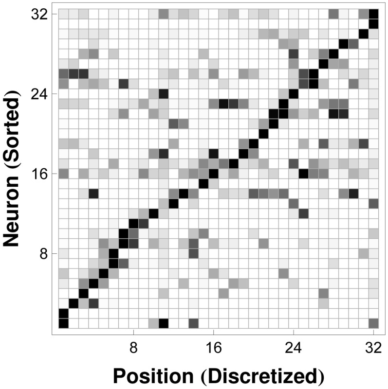
  equal-length intervals along a one-dimensional track maze. Neurons (rows) have been sorted according to their positions of maximal activity to illustrate that the receptive fields of the place cells in this population cover the one-dimensional space of interest. Neuronal spike rates for each cell in each state (row elements) have been normalized to the highest spike rate (maximal row element) exhibited by the particular cell over all states. (Black: Maximal Spike Rate, White: Zero Spike Rate, Gray: Intermediate Spike Rates.).
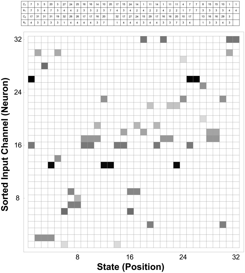
 stored in system memory, resulting in the output shown in Figure 5, using the
  most informative threshold values for each position state. Some elements of the rule table (three pair) are empty, with corresponding columns having fewer than
  nonwhite elements, because the associated states had fewer than
  channels able to satisfy
  and
and  , the minimum sensitivity and positive predictive value, respectively, for state decoding. (White: Unused, Light Gray:
  Spike per
  -ms Window, Black:
  Spikes per
  -ms Window.) Intuitively, this set of templates can be understood as the tape-reading rules for a Turing machine, whose symbols are generated by the time-windowed spike counts on neural input channels, and whose states correspond to a discretized set of position states encoded by the underlying neuronal populations. At each time step, the neural decoder scans down each column in the array to determine the states, if any, whose rules have been satisfied; the decoded output elements
  are set to
  for those states, and to
  otherwise. The rules displayed graphically in the rectangular array are encoded numerically in the table displayed above the array (which is reproduced in Table 1). The columns of the table are aligned with the states in the array for which they contain decoding data, comprising the indices of the two most informative channels,
  and
and  , and the corresponding spike thresholds,
  and
and  .
.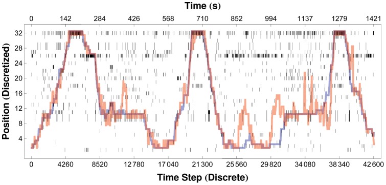
 , is shown as a raster array, with the output at each time step displayed as a vertical column of pixels (black pixels correspond to
  , white pixels to
  ). Red lines show the trajectories obtained after applying our Viterbi algorithm to the raw decoder output, as described in the text. The actual trajectories of the rat are shown in blue. Decoding accuracy and decoder noise are affected by the length of the time window over which spikes are collected at each time step:
  ms (
ms ( ms). Here the decoded trajectory matches the actual trajectory with a correlation coefficient of
  .
.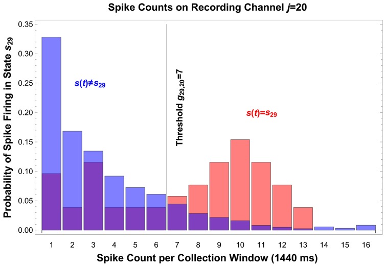
 , demonstrates that a threshold of
  spikes per
  -ms window, on recording channel
  , is sensitive and specific for state
  (Sensitivity:
  , Specificity:
  , Positive Predictive Value:
  ). This threshold is written on the threshold tape used to program the internal unit of the decoder, and can be seen numerically in Figure 4 as the
  and
and  row entries of column
  , and graphically as the corresponding pixels in the rule array.
References
-
- Patil PG (2009) Introduction: Advances in brain-machine interfaces. Neurosurgical Focus 27: E1. - PubMed
-
- Nicolelis MAL (2003) Brain–machine interfaces to restore motor function and probe neural circuits. Nature Reviews Neuroscience 4: 417–422. - PubMed
-
- Schwartz A, Cui XT, Weber D, Moran D (2006) Brain-controlled interfaces: Movement restoration with neural prosthetics. Neuron 56: 205–220. - PubMed
-
- Hochberg LR, Serruya MD, Friehs GM, Mukand JA, Saleh M, et al. (2006) Neuronal ensemble control of prosthetic devices by a human with tetraplegia. Nature 442: 164–171. - PubMed
-
- Chader GJ, Weiland J, Humayun MS (2009) Artificial vision: needs, functioning, and testing of a retinal electronic prosthesis. Neurotherapy: Progress in Restorative Neuroscience and Neurology 175: 317–332. - PubMed
Publication types
MeSH terms
Grants and funding
LinkOut - more resources
Full Text Sources
Other Literature Sources
