

Do obesity and/or stripe wear increase ceramic liner fracture risk? An XFEM analysis
- PMID: 23008021
- PMCID: PMC3549159
- DOI: 10.1007/s11999-012-2562-6
Do obesity and/or stripe wear increase ceramic liner fracture risk? An XFEM analysis
Abstract
Background: Hypothesized risk factors for fracture of ceramic liners include impingement, edge-loading, and cup malpositioning. These risk factors are similar to those for generation of stripe wear. However, it is unclear whether the biomechanical conditions contributing to stripe wear generation also increase the risk for ceramic liner fracture
Questions/purposes: We asked whether (1) head stripe wear propensity; and (2) cup orientation would correlate with alumina liner fracture risk for instances of normal and elevated body weight.
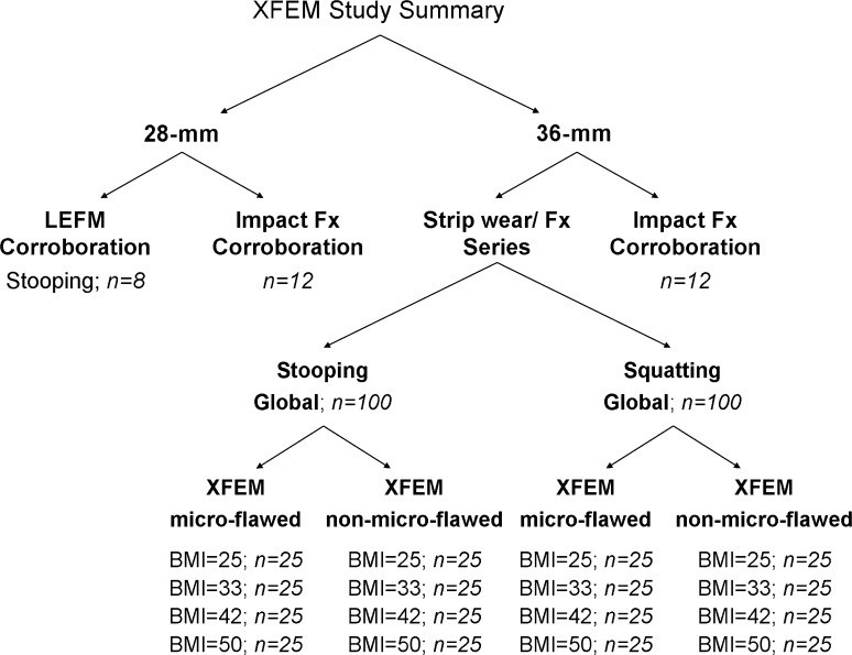
Methods: An eXtended Finite Element Method (XFEM) model was developed to investigate these mechanisms. Liner fracture risk for 36-mm alumina bearings was studied by simulating two fracture-prone motions: stooping and squatting. Twenty-five distinct cup orientations were considered with variants of both acetabular inclination and anteversion. Four separate body mass indices were considered: normal (25 kg/m(2)) and three levels of obesity (33, 42, and 50 kg/m(2)). Material properties were modified to simulate alumina with and without the presence of dispersed microflaws. The model was validated by corroboration with two previously published ceramic liner fracture studies.
Results: Of 200 XFEM simulations with flaw-free alumina, fracture occurred in eight instances, all of them involving obesity. Each of these occurred with cups in ≤ 37° inclination and in 0° anteversion. For 200 corresponding simulations with microflawed alumina, fracture propensity was greatest for cups with higher (edge loading-associated) scraping wear. Fracture risk was greatest for cups with lower inclination (average 42° for fractured cases versus 48° for nonfractured cases) and lower anteversion (9° versus 20°).
Conclusions: Fracture propensity for 36-mm liners was elevated for cups with decreased anteversion and/or inclination and under conditions of patient obesity.
Clinical relevance: Factors causing stripe wear, including obesity and cup malpositioning, also involve increased risk of ceramic liner fracture and merit heightened concern.
Figures


Similar articles
-
Failure analysis of a ceramic bearing acetabular component.J Bone Joint Surg Am. 2007 Feb;89(2):367-75. doi: 10.2106/JBJS.F.00148. J Bone Joint Surg Am. 2007. PMID: 17272452
-
Delayed diagnosis of low-symptomatic ceramic acetabular liner fracture in ceramic-on-ceramic total hip arthroplasty.Orthopedics. 2008 Oct;31(10):orthosupersite.com/view.asp?rID=31523. Orthopedics. 2008. PMID: 19226001
-
Fracture propagation propensity of ceramic liners during impingement-subluxation: a finite element exploration.J Arthroplasty. 2012 Apr;27(4):520-6. doi: 10.1016/j.arth.2011.06.023. Epub 2011 Aug 19. J Arthroplasty. 2012. PMID: 21855277 Free PMC article.
-
Ceramic on ceramic total hip arthroplasty and liner fracture. Two case reports and review of literature.Acta Biomed. 2019 Dec 5;90(12-S):192-195. doi: 10.23750/abm.v90i12-S.8961. Acta Biomed. 2019. PMID: 31821308 Free PMC article. Review.
-
Does Biolox Delta ceramic reduce the rate of component fractures in total hip replacement?Orthop Traumatol Surg Res. 2014 Oct;100(6 Suppl):S317-21. doi: 10.1016/j.otsr.2014.05.010. Epub 2014 Aug 12. Orthop Traumatol Surg Res. 2014. PMID: 25130763 Review.
Cited by
-
Ceramic head fracture in ceramic-on-polyethylene total hip arthroplasty.Yonsei Med J. 2013 Nov;54(6):1550-3. doi: 10.3349/ymj.2013.54.6.1550. Yonsei Med J. 2013. PMID: 24142666 Free PMC article.
-
Forte ceramic-on-delta ceramic cementless total hip arthroplasty: an 8- to 15-year follow-up study.Arch Orthop Trauma Surg. 2023 Sep;143(9):5475-5483. doi: 10.1007/s00402-023-04793-2. Epub 2023 Mar 5. Arch Orthop Trauma Surg. 2023. PMID: 36871241
-
Do the Reasons for Ceramic-on-ceramic Revisions Differ From Other Bearings in Total Hip Arthroplasty?Clin Orthop Relat Res. 2016 Oct;474(10):2190-9. doi: 10.1007/s11999-016-4917-x. Clin Orthop Relat Res. 2016. PMID: 27255729 Free PMC article.
-
Mid term results of total hip arthroplasty using polyethylene-ceramic composite (Sandwich) liner.Indian J Orthop. 2016 Jan-Feb;50(1):10-5. doi: 10.4103/0019-5413.173512. Indian J Orthop. 2016. PMID: 26952027 Free PMC article.
-
Catastrophic ceramic liner failure-The subtle signs of a non-engaged ceramic liner.J Orthop. 2018 Feb 20;15(2):363-365. doi: 10.1016/j.jor.2018.02.004. eCollection 2018 Jun. J Orthop. 2018. PMID: 29881154 Free PMC article.
References
-
- Archard J. Contact and rubbing of flat surfaces. J Appl Phys. 1953;24:981–988. doi: 10.1063/1.1721448. - DOI
-
- Brockett C, Williams S, Jin Z, Isaac G, Fisher J. Friction of total hip replacements with different bearings and loading conditions. J Biomed Mater Res B Appl Biomater. 2007;81:508–515. - PubMed
-
- Budyn E, Hoc T. Multiple scale modeling of cortical bone fracture in tension using X-FEM. Eur J Comput Mech v16. 2007;16:215–238.
Publication types
MeSH terms
Grants and funding
LinkOut - more resources
Full Text Sources
Other Literature Sources
Medical
