. 2011 Mar;3(2):158-69.
doi: 10.1177/1941738111399372.

Patellofemoral disorders: role of computed tomography and magnetic resonance imaging in defining abnormal rotational lower limb alignment

Affiliations

Patellofemoral disorders: role of computed tomography and magnetic resonance imaging in defining abnormal rotational lower limb alignment

Shital Parikh et al. Sports Health. 2011 Mar.

Abstract

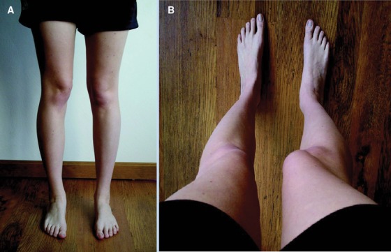
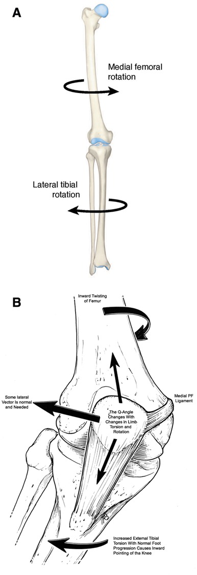
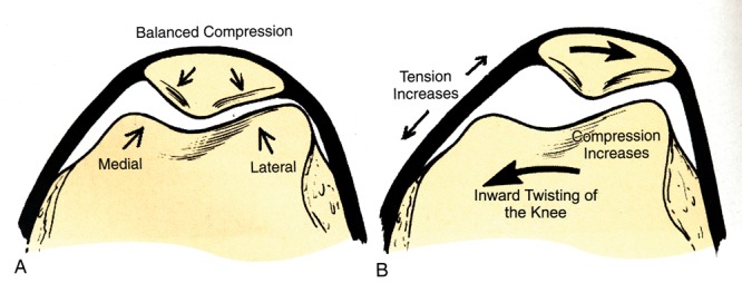
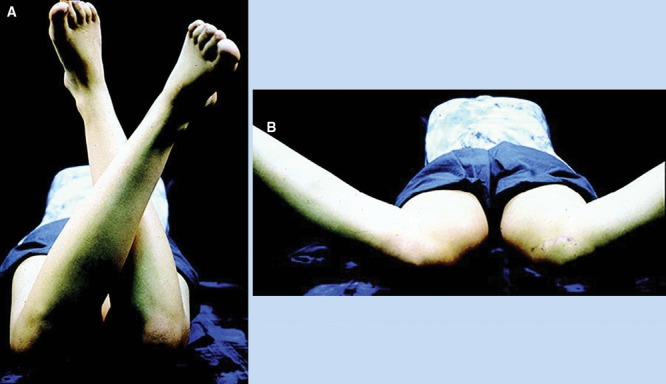
Background: The contribution of lower limb rotational malalignment to patellofemoral pain and instability has been well recognized. The purpose of the present study is to review the role of computed tomography (CT) and magnetic resonance imaging (MRI) in assessment of abnormal rotational alignment of lower limb.

Evidence acquisition: An analysis of all available literature in the English language through 2010 was performed to provide data on a comparison between MRI and CT-specifically, the techniques and normative values used to determine abnormal lower limb alignment.

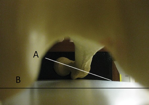
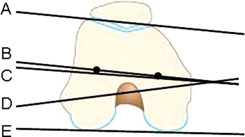
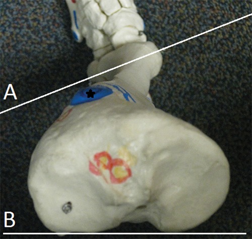
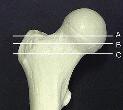
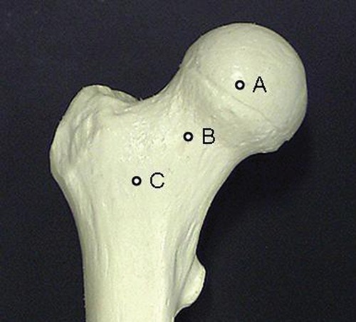
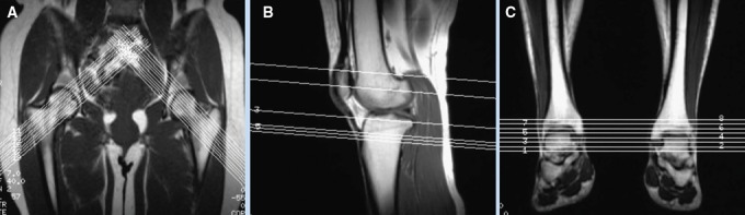
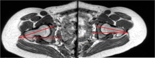
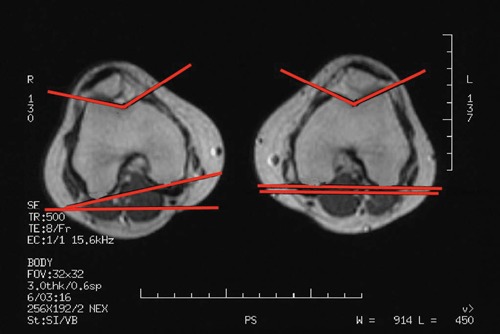
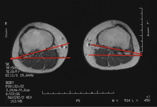
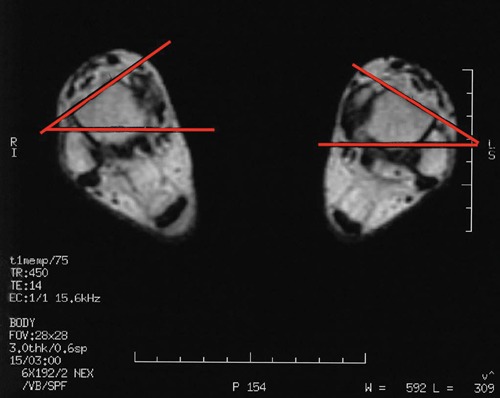
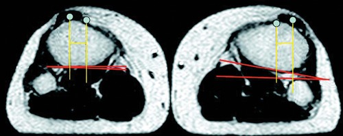
Results: CT and MRI are highly accurate in defining abnormal alignment of the lower limb. Determination of axis of femoral anteversion in proximal femur has been the subject of debate in the literature. The determination of distal femoral condylar axis, proximal tibial axis and distal tibial axis are less controversial.

Conclusions: CT and MRI are both used for assessing the rotational abnormalities of the femur and tibia during evaluation for patellofemoral disorders. MRI has an advantage over CT because femoral anteversion measurements are more accurate and ionizing radiation is avoided. A standardized protocol defining the level and axes for measurement of femoral and tibial alignment indices should be used to maintain consistency in measurements.

Keywords: computed tomography; femoral anteversion; magnetic resonance imaging; patellofemoral pain; tibial torsion.


Conflict of interest statement

No potential conflict of interest declared.

Figures

Figure 1.
Figure 1.
Miserable malalignment syndrome. The patient often presents with medial parapatellar pain with no localizing findings or images indicating pathology: A, when viewed from the front, the squinting patella on the right is well visualized, with both femurs having greater than 50° anteversion; B, what the patient sees looking down her legs. Used with permission.
Figure 2.
Figure 2.
A, overall lower limb alignment shows the inward torsion of the femur attributed to increased femoral anteversion and compensatory tibial rotation. B, the effect of this lower limb alignment, resulting in abnormal patellofemoral loads and tendency for lateral subluxation. Used with permission.
Figure 3.
Figure 3.
A, when the knee faces forward with normal foot progression, the patellofemoral joint forces are balanced. B, when the knee faces inward with normal foot progression, the medial patellofemoral ligament tension and forces on lateral patellar facet are increased, whereas the forces on medial facet are decreased. Used with permission.
Figure 4.
Figure 4.
A femur through the intercondylar notch with posterior femoral condyles on a flat surface shows femoral anteversion. Line A (proximal femur) represents the axis of the femoral neck, which is angled anteriorly in relationship to line B (distal femur), representing the tangent to posterior femoral condyles.
Figure 5.
Figure 5.
Axes to determine the condylar plane: B, the axes through the centroid of medial and lateral femoral condyle; C, the bisector between tangents A (anterior) and E (posterior); D, the widest diameter through the medial and lateral condyle; E, the tangent through the posterior aspect of the femoral condyles (the most frequently used for determining condylar axes).
Figure 6.
Figure 6.
Tibia from top shows tibial torsion. Line A (distal tibia) is externally rotated in relationship to line B (proximal tibia), representing the twist in tibia. The position of tibial tubercle (star) shows that majority of the twist occurs in the proximal tibia.
Figure 7.
Figure 7.
Decreased external rotation (A) and increased internal rotation (B) suggests femoral anteversion. Used with permission.
Figure 8.
Figure 8.
Single transverse sections at various levels have been used for determination of femoral anteversion axes. Section B, as described by Weiner et al, passes through femoral head and neck but underestimates the true anteversion. Section C, as described by Sugano et al, passes just inferior to the femoral head and approximates the true anteversion measurements. The more proximal the section (ie, section A), the greater the underestimation of femoral anteversion.
Figure 9.
Figure 9.
Superimposition of transverse images through different levels for determination of femoral anteversion axes. Section through the center of femoral head (A) and femoral neck (B), as described by Reikeras et al, underestimates the femoral anteversion measurements. Section through the center of femoral head (A) and base of the neck (C), as described by Murphy, overestimates the true anteversion measurements.
Figure 10.
Figure 10.
Axial (oblique) images through the femoral neck give the most accurate estimate of femoral anteversion. With the patient in supine position, with symmetric positioning of both lower extremities, and with hips and knees in extension, a coronal-section scout view of pelvis and femur is obtained, parallel to the table. Oblique axial-to-sagittal sections can then be placed parallel to the femoral neck axis, exactly perpendicular to the table. The femoral neck anteversion is determined on the single image, which shows the center of the femoral head and femoral neck.
Figure 11.
Figure 11.
Scout MRI views showing the level and axis of sections performed for assessment of femoral neck axis (A), distal femoral and proximal tibial axis (B), and talar axis (C). Used with permission.
Figure 12.
Figure 12.
Femoral neck axis is drawn on the section through the center of femoral head and femoral neck, and its angle with a transverse axis is measured.
Figure 13.
Figure 13.
The proximal tibial axis is determined by a tangent to the posterior aspect of the proximal tibia, just below the articular surface and above the level of fibula. Used with permission.
Figure 14.
Figure 14.
The proximal tibial axis is determined by a tangent to the posterior aspect of the proximal tibia, just below the articular surface and above the level of fibula. Used with permission.
Figure 15.
Figure 15.
The tangent to the anterior surface of the talus determines the distal axis for tibial torsion measurement. Used with permission.
Figure 16.
Figure 16.
Measurement of tibial tubercle–trochlear groove distance. The section is through the insertion site of patellar tendon. Used with permission.

References

    1. Bauman PA, Singson R, Hamilton WG. Femoral neck anteversion in ballerinas. Clin Orthop. 1994;302:57-63 - PubMed
    1. Beaconsfield T, Pintore E, Maffulli N, Petri GJ. Radiological measurements in patellofemoral disorders: a review. Clin Orthop. 1994;308:18-28 - PubMed
    1. Billing L. Roentgen examination of the proximal femur end in children and adolescents: a standardized technique also suitable for determination of the collum, anteversion and epiphyseal angles. A study of slipped epiphysis and coxa plana. Acta Radiol. 1954;110(suppl):1 - PubMed
    1. Bruce WD, Stevens PM. Surgical correction of miserable malalignment syndrome. J Pediatr Orthop. 2004;24(4):1-5 - PubMed
    1. Chung CY, Lee KM, Park S, et al. Validity and reliability of measuring femoral anteversion and neck-shaft angle in patients with cerebral palsy. J Bone Joint Surg Am. 2010;92:1195-1205 - PubMed