

Total shoulder arthroplasty does not correct the orientation of the eroded glenoid
- PMID: 23083436
- PMCID: PMC3488182
- DOI: 10.3109/17453674.2012.733916
Total shoulder arthroplasty does not correct the orientation of the eroded glenoid
Abstract
Background and purpose: Alignment of the glenoid component with the scapula during total shoulder arthroplasty (TSA) is challenging due to glenoid erosion and lack of both bone stock and guiding landmarks. We determined the extent to which the implant position is governed by the preoperative erosion of the glenoid. Also, we investigated whether excessive erosion of the glenoid is associated with perforation of the glenoid vault.
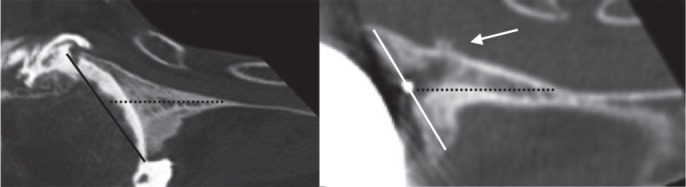
Methods: We used preoperative and postoperative CT scans of 29 TSAs to assess version, inclination, rotation, and offset of the glenoid relative to the scapula plane. The position of the implant keel within the glenoid vault was classified into three types: centrally positioned, component touching vault cortex, and perforation of the cortex.
Results: Preoperative glenoid erosion was statistically significantly linked to the postoperative placement of the implant regarding all position parameters. Retroversion of the eroded glenoid was on average 10° (SD10) and retroversion of the implant after surgery was 7° (SD11). The implant keel was centered within the vault in 7 of 29 patients and the glenoid vault was perforated in 5 patients. Anterior cortex perforation was most frequent and was associated with severe preoperative posterior erosion, causing implant retroversion.
Interpretation: The position of the glenoid component reflected the preoperative erosion and "correction" was not a characteristic of the reconstructive surgery. Severe erosion appears to be linked to vault perforation. If malalignment and perforation are associated with loosening, our results suggest reorientation of the implant relative to the eroded surface.
Figures


Similar articles
-
Vault perforation after eccentric glenoid reaming for deformity correction in anatomic total shoulder arthroplasty.J Shoulder Elbow Surg. 2020 Jul;29(7):1450-1459. doi: 10.1016/j.jse.2019.11.011. Epub 2020 Feb 12. J Shoulder Elbow Surg. 2020. PMID: 32061513
-
Angled BIO-RSA (bony-increased offset-reverse shoulder arthroplasty): a solution for the management of glenoid bone loss and erosion.J Shoulder Elbow Surg. 2017 Dec;26(12):2133-2142. doi: 10.1016/j.jse.2017.05.024. Epub 2017 Jul 20. J Shoulder Elbow Surg. 2017. PMID: 28735842
-
A scapular statistical shape model can reliably predict premorbid glenoid morphology in conditions of severe glenoid bone loss.J Shoulder Elbow Surg. 2024 Nov;33(11):2493-2504. doi: 10.1016/j.jse.2024.03.060. Epub 2024 May 16. J Shoulder Elbow Surg. 2024. PMID: 38762148
-
Current concepts in the surgical management of primary glenohumeral arthritis with a biconcave glenoid.J Shoulder Elbow Surg. 2013 Nov;22(11):1589-98. doi: 10.1016/j.jse.2013.06.017. Epub 2013 Sep 3. J Shoulder Elbow Surg. 2013. PMID: 24007651 Review.
-
Addressing glenoid erosion in anatomic total shoulder arthroplasty.Bull Hosp Jt Dis (2013). 2013;71 Suppl 2:S46-50. Bull Hosp Jt Dis (2013). 2013. PMID: 24328580 Review.
Cited by
-
Soft tissue balancing in total shoulder replacement.Curr Rev Musculoskelet Med. 2014 Mar;7(1):16-21. doi: 10.1007/s12178-013-9195-6. Curr Rev Musculoskelet Med. 2014. PMID: 24390706 Free PMC article.
-
Shoulder Arthroplasty Imaging: What's New.Open Orthop J. 2017 Sep 30;11:1126-1132. doi: 10.2174/1874325001711011126. eCollection 2017. Open Orthop J. 2017. PMID: 29152007 Free PMC article. Review.
-
Short, Medium and Long Term Complications After Total Anatomical Shoulder Arthroplasty.Open Orthop J. 2017 Sep 30;11:1133-1141. doi: 10.2174/1874325001711011133. eCollection 2017. Open Orthop J. 2017. PMID: 29152008 Free PMC article. Review.
-
3D printing in shoulder surgery.Orthop Rev (Pavia). 2020 Jun 26;12(Suppl 1):8681. doi: 10.4081/or.2020.8681. eCollection 2020 Jun 29. Orthop Rev (Pavia). 2020. PMID: 32913609 Free PMC article.
-
The Glenoid Vault Outer Cortex a new more accurate radiological reference for shoulder arthroplasty.SICOT J. 2021;7:32. doi: 10.1051/sicotj/2021030. Epub 2021 May 19. SICOT J. 2021. PMID: 34009116 Free PMC article.
References
-
- Amadi HO, Hansen UN, Wallace AL, Bull AM. A scapular coordinate frame for clinical and kinematic analyses. J Biomech. 2008;41(10):2144–9. - PubMed
-
- Bohsali KI, Wirth MA, Rockwood C A., Jr Complications of total shoulder arthroplasty. J Bone Joint Surg (Am) 2006;88(10):2279–92. - PubMed
-
- Churchill RS, Brems JJ, Kotschi H. Glenoid size, inclination, and version: Anatomical study. J Shoulder Elbow Surg. 2001;10(4):327–32. - PubMed
-
- Codsi MJ, Bennetts C, Gordiev K, Boeck DM, Known YW, Brems JJ. Normal glenoid vault anatomy and validation of a novel glenoid implant shape. J Shoulder Elbow Surg. 2008;17(3):471–8. - PubMed
-
- Farron A, Terrier A, Buchler P. Risks of loosening of a prosthetic glenoid implanted in retroversion. J Shoulder Elbow Surg. 2006;15(4):521–6. - PubMed
Publication types
MeSH terms
LinkOut - more resources
Full Text Sources
Medical
Research Materials