

A computational framework for investigating the positional stability of aortic endografts
- PMID: 23143353
- PMCID: PMC3638896
- DOI: 10.1007/s10237-012-0450-3
A computational framework for investigating the positional stability of aortic endografts
Abstract
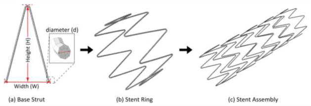
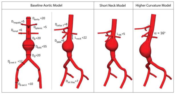
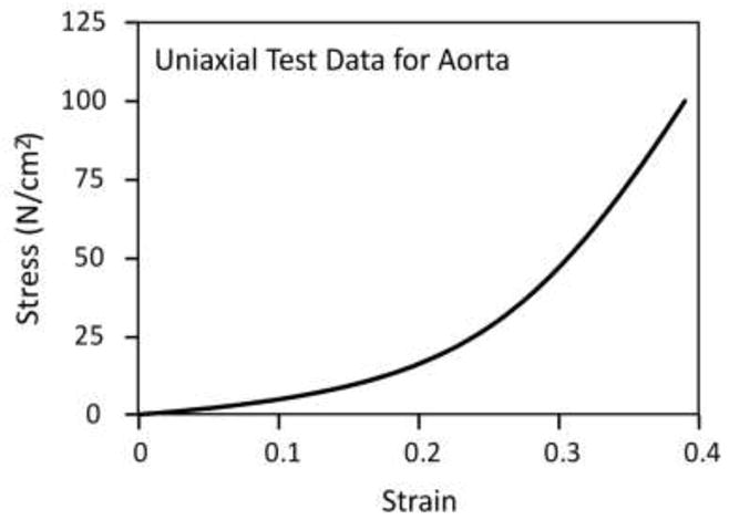
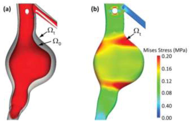
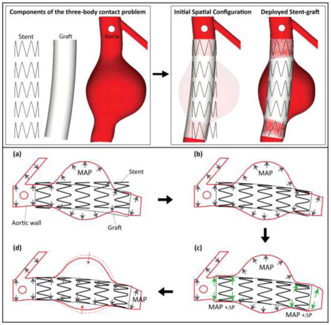
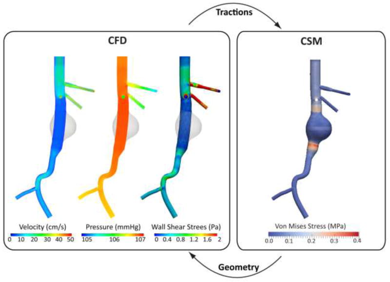
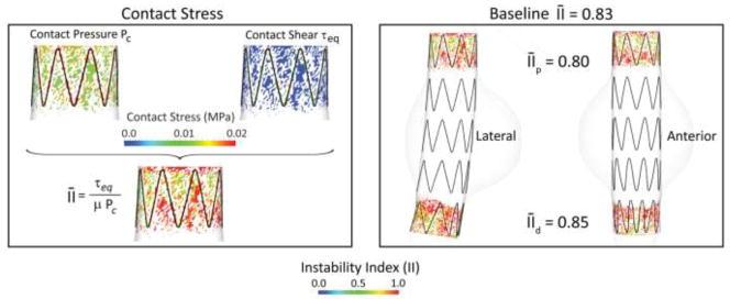
Endovascular aneurysm repair (Greenhalgh in N Engl J Med 362(20):1863-1871, 2010) techniques have revolutionized the treatment of thoracic and abdominal aortic aneurysm disease, greatly reducing the perioperative mortality and morbidity associated with open surgical repair techniques. However, EVAR is not free of important complications such as late device migration, endoleak formation and fracture of device components that may result in adverse events such as aneurysm enlargement, need for long-term imaging surveillance and secondary interventions or even death. These complications result from the device inability to withstand the hemodynamics of blood flow and to keep its originally intended post-operative position over time. Understanding the in vivo biomechanical working environment experienced by endografts is a critical factor in improving their long-term performance. To date, no study has investigated the mechanics of contact between device and aorta in a three-dimensional setting. In this work, we developed a comprehensive Computational Solid Mechanics and Computational Fluid Dynamics framework to investigate the mechanics of endograft positional stability. The main building blocks of this framework are: (1) Three-dimensional non-planar aortic and stent-graft geometrical models, (2) Realistic multi-material constitutive laws for aorta, stent, and graft, (3) Physiological values for blood flow and pressure, and (4) Frictional model to describe the contact between the endograft and the aorta. We introduce a new metric for numerical quantification of the positional stability of the endograft. Lastly, in the results section, we test the framework by investigating the impact of several factors that are clinically known to affect endograft stability.
Figures
Similar articles
-
Computational analysis of stresses acting on intermodular junctions in thoracic aortic endografts.J Endovasc Ther. 2011 Aug;18(4):559-68. doi: 10.1583/11-3472.1. J Endovasc Ther. 2011. PMID: 21861748 Free PMC article.
-
Fenestrated endovascular grafts for the repair of juxtarenal aortic aneurysms: an evidence-based analysis.Ont Health Technol Assess Ser. 2009;9(4):1-51. Epub 2009 Jul 1. Ont Health Technol Assess Ser. 2009. PMID: 23074534 Free PMC article.
-
Dynamic seal at the aortic neck-endograft interface studied using a novel method of cohesive zone modeling.J Vasc Surg. 2020 Aug;72(2):703-713.e3. doi: 10.1016/j.jvs.2019.07.101. Epub 2019 Nov 11. J Vasc Surg. 2020. PMID: 31727454
-
Complications of endovascular aneurysm repair of the thoracic and abdominal aorta: evaluation and management.Cardiovasc Diagn Ther. 2018 Apr;8(Suppl 1):S138-S156. doi: 10.21037/cdt.2017.09.17. Cardiovasc Diagn Ther. 2018. PMID: 29850426 Free PMC article. Review.
-
Endovascular stent grafting and open surgical replacement for chronic thoracic aortic aneurysms: a systematic review and prospective cohort study.Health Technol Assess. 2022 Jan;26(6):1-166. doi: 10.3310/ABUT7744. Health Technol Assess. 2022. PMID: 35094747
Cited by
-
Stent-graft surface movement after endovascular aneurysm repair: baseline parameters for prediction, and association with migration and stent-graft-related endoleaks.Eur Radiol. 2019 Dec;29(12):6385-6395. doi: 10.1007/s00330-019-06282-w. Epub 2019 Jun 27. Eur Radiol. 2019. PMID: 31250169 Free PMC article.
-
Efficiently Simulating an Endograft Deployment: A Methodology for Detailed CFD Analyses.Ann Biomed Eng. 2020 Oct;48(10):2449-2465. doi: 10.1007/s10439-020-02519-8. Epub 2020 May 11. Ann Biomed Eng. 2020. PMID: 32394221 Free PMC article.
-
Mechanisms of aortic dissection: From pathological changes to experimental and in silico models.Prog Mater Sci. 2025 Apr;150:101363. doi: 10.1016/j.pmatsci.2024.101363. Epub 2024 Sep 12. Prog Mater Sci. 2025. PMID: 39830801 Free PMC article.
-
Functional assessment of thoracic aortic aneurysms - the future of risk prediction?Br Med Bull. 2017 Jan 1;121(1):61-71. doi: 10.1093/bmb/ldw049. Br Med Bull. 2017. PMID: 27989994 Free PMC article. Review.
-
Haemodynamic Analysis of Branched Endografts for Complex Aortic Arch Repair.Bioengineering (Basel). 2022 Jan 18;9(2):45. doi: 10.3390/bioengineering9020045. Bioengineering (Basel). 2022. PMID: 35200399 Free PMC article.
References
-
- Ahrens J, Geveci B, et al. ParaView: An end-user tool for large data visualization. 2005.
-
- Albertini JN, Kalliafas S, et al. Anatomical risk factors for proximal perigraft endoleak and graft migration following endovascular repair of abdominal aortic aneurysms. European Journal of Vascular and Endovascular Surgery. 2000;19(3):308–312. - PubMed
-
- Amblard A, Berre HWL, et al. Analysis of type I endoleaks in a stented abdominal aortic aneurysm. Medical Engineering & Physics. 2009;31(1):27–33. - PubMed
-
- Arko FR, Heikkinen M, et al. Iliac fixation length and resistance to in-vivo stent-graft displacement. Journal of Vascular Surgery. 2005;41(4):664–670. - PubMed
-
- Brewster DC, Cronenwett JL, et al. Guidelines for the treatment of abdominal aortic aneurysms: Report of a subcommittee of the Joint Council of the American Association for Vascular Surgery and Society for Vascular Surgery. Journal of Vascular Surgery. 2003;37(5):1106–1117. - PubMed
Publication types
MeSH terms
Grants and funding
LinkOut - more resources
Full Text Sources
