. 2012:2:857.
doi: 10.1038/srep00857. Epub 2012 Nov 15.

Development of miniaturized walking biological machines

Affiliations

Development of miniaturized walking biological machines

Vincent Chan et al. Sci Rep. 2012.

Abstract

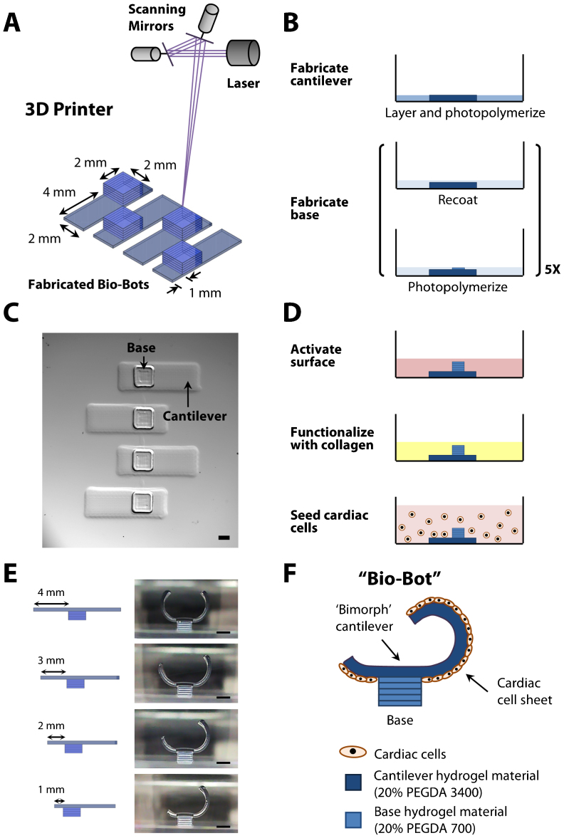
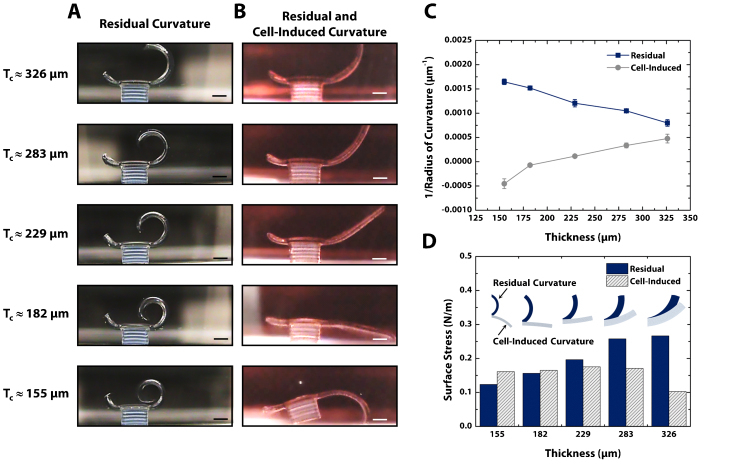
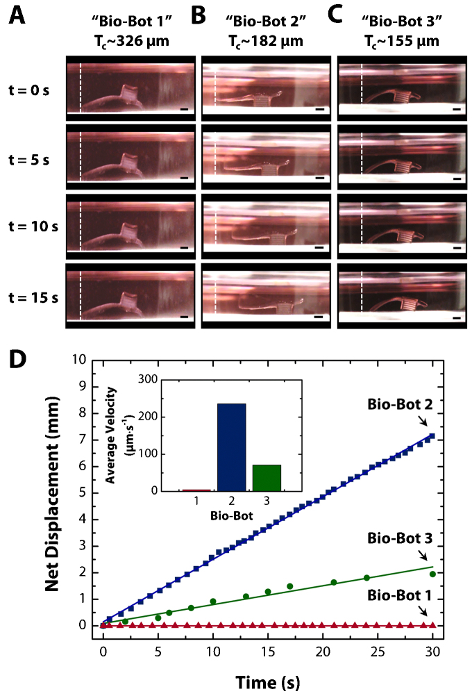
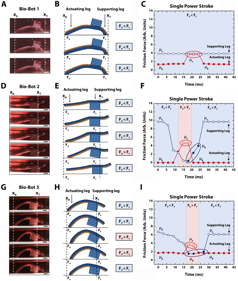
The quest to 'forward-engineer' and fabricate biological machines remains a grand challenge. Towards this end, we have fabricated locomotive "bio-bots" from hydrogels and cardiomyocytes using a 3D printer. The multi-material bio-bot consisted of a 'biological bimorph' cantilever structure as the actuator to power the bio-bot, and a base structure to define the asymmetric shape for locomotion. The cantilever structure was seeded with a sheet of contractile cardiomyocytes. We evaluated the locomotive mechanisms of several designs of bio-bots by changing the cantilever thickness. The bio-bot that demonstrated the most efficient mechanism of locomotion maximized the use of contractile forces for overcoming friction of the supporting leg, while preventing backward movement of the actuating leg upon relaxation. The maximum recorded velocity of the bio-bot was ~236 µm s(-1), with an average displacement per power stroke of ~354 µm and average beating frequency of ~1.5 Hz.


Figures

Figure 1
Figure 1. Fabrication and cell seeding methods.
(a) Diagram of 3D stereo-lithographic printer consisting of a HeCd laser at 325 nm and galvanometer scanning mirrors. The mirrors are computer-controlled, and a stage lowers the part a specified distance after each layer. (b) Process flow diagram for high-throughput array of bio-bots. (c) Representative top-down images depicting an array of fabricated bio-bots with cantilever and base structures. (d) Process flow diagram for functionalization of the cantilevers with collagen and seeding of cardiac cells. (e) Representative cross-sectional images depicting iterative bio-bot designs from symmetry-to-asymmetry. (f) Diagram of final bio-bot design consisting of biological bimorph cantilever with seeded cardiac cell sheet. All scale bars are 1 mm.
Figure 2
Figure 2. Design of bio-bots through residual and cell-induced surface stresses.
(a) Representative cross-sectional images of bio-bots with varying cantilever thicknesses. After overnight swelling, the residual stresses cause the cantilevers to curl upward, depending on the thickness of the cantilever. (b) Representative cross-sectional images of bio-bots three days after cardiac cell seeding on the cantilever side facing the base. Cytoskeletal tension from the cells causes the cantilever to curl downward to a final bio-bot shape. (c) Plot of inverse radius of curvature vs. cantilever thickness for residual (pre-seeded) and residual + cell-induced curvature (post-seeded). (d) Plot of surface stress vs. cantilever thickness for residual and residual + cell-induced curvature. All scale bars are 1 mm.
Figure 3
Figure 3. Demonstrations of bio-bot locomotion.
(a–c) Time course of net forward motion for “bio-bot 1” (326 μm thick), “bio-bot 2” (182 μm thick), and “bio-bot 3” (155 μm thick) over 5 second intervals for a period of 15 seconds. (d) Plot of net displacement vs. time for all three bio-bot designs. The inset is a plot of average velocity vs. bio-bot design, which is extracted from the plot of net displacement vs. time. All scale bars are 1 mm.
Figure 4
Figure 4. Mechanisms of bio-bot locomotion.
(a) Representative cross-sectional images of a bio-bot 1 power stroke. (b) Step-by-step diagram of bio-bot 1 power stroke depicting no change between the friction forces of the actuating (Fa) and supporting legs (Fs), which results in no net forward motion. (c) Plot of friction force vs. time for a single power stroke of bio-bot 1 showing the change between the coefficients of static friction (µs, open fill) and kinetic friction (µk, solid fill). (d) Representative cross-sectional images of a bio-bot 2 power stroke. (e) Step-by-step diagram of bio-bot 2 power stroke depicting changes between Fa and Fs, which results in net forward motion. (f) Plot of friction force vs. time for a single power stroke of bio-bot 2 showing changes in µs (open fill) and µk (solid fill). (g) Representative cross-sectional images of a bio-bot 3 power stroke. (h) Step-by-step diagram of bio-bot 3 power stroke depicting changes between Fa and Fs, which results in net forward motion. (i) Plot of friction force vs. time for a single power stroke of bio-bot 3 showing changes in µs (open fill) and µk (solid fill). All scale bars are 1 mm.

References

    1. Basu S., Gerchman Y., Collins C. H., Arnold F. H. & Weiss R. A synthetic multicellular system for programmed pattern formation. Nature 434, 1130–1134 (2005). - PubMed
    1. Kamm R. D., Nerem R. M. & Hsia K. J. Cells into systems. Mech. Eng. 30–34 (2010).
    1. Lutolf M. P. & Hubbell J. A. Synthetic biomaterials as instructive extracellular microenvironments for morphogenesis in tissue engineering. Nat. Biotechnol. 23, 47–55 (2005). - PubMed
    1. Chung S., Lee J. H., Moon M. W., Han J. & Kamm R. D. Non-lithographic wrinkle nanochannels for protein preconcentration. Adv. Mater. 20, 3011–3016 (2008).
    1. Grzybowski B. A. & Bishop K. J. Micro- and nanoprinting into solids using reaction diffusion etching and hydrogel stamps. Small 5, 22–27 (2009). - PubMed

Publication types