

Non-polarizing broadband multilayer reflectors in fish
- PMID: 23160173
- PMCID: PMC3496938
- DOI: 10.1038/nphoton.2012.260
Non-polarizing broadband multilayer reflectors in fish
Abstract
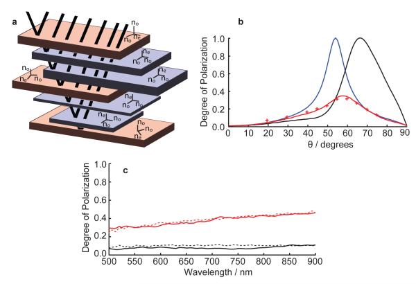
Dielectric multilayer reflectors that are non-polarizing are an important class of optical device and have numerous applications within optical fibres [1], dielectric waveguides [2] and LEDs [3]. Here we report analyses of a biological non-polarizing optical mechanism found in the broadband guanine-cytoplasm "silver" multilayer reflectors of three species of fish. Present in the fish stratum argenteum are two populations of birefringent guanine crystal, each with their optic axes either parallel to the long axis of the crystal or perpendicular to the plane of the crystal. This arrangement neutralizes the polarization of reflection due the different interfacial Brewster's angles of each population. The fish reflective mechanism is distinct from existing non-polarizing mirror designs [4, 5, 6, 7] with the important feature that there is no refractive index contrast between the low index layers in the reflector and the external environment. It is a mechanism that could be readily manufactured and exploited in synthetic optical devices.
Figures


Similar articles
-
Assembly of Guanine Crystals as a Low-Polarizing Broadband Multilayer Reflector in a Spider, Phoroncidia rubroargentea.ACS Appl Mater Interfaces. 2022 Jul 27;14(29):32982-32993. doi: 10.1021/acsami.2c09546. Epub 2022 Jul 14. ACS Appl Mater Interfaces. 2022. PMID: 35834638
-
Disordered animal multilayer reflectors and the localization of light.J R Soc Interface. 2014 Dec 6;11(101):20140948. doi: 10.1098/rsif.2014.0948. J R Soc Interface. 2014. PMID: 25339688 Free PMC article.
-
Multilayer dielectric reflector using low-index nanolattices.Opt Lett. 2024 Feb 15;49(4):1093-1096. doi: 10.1364/OL.516147. Opt Lett. 2024. PMID: 38359261
-
Giant birefringent optics in multilayer polymer mirrors.Science. 2000 Mar 31;287(5462):2451-6. doi: 10.1126/science.287.5462.2451. Science. 2000. PMID: 10741958
-
Reconfigurable broadband infrared circularly polarizing reflectors based on phase changing birefringent metasurfaces.Opt Express. 2013 Jan 14;21(1):1087-100. doi: 10.1364/OE.21.001087. Opt Express. 2013. PMID: 23389002
Cited by
-
Hyperspectral interference tomography of nacre.Proc Natl Acad Sci U S A. 2021 Apr 13;118(15):e2023623118. doi: 10.1073/pnas.2023623118. Proc Natl Acad Sci U S A. 2021. PMID: 33833057 Free PMC article.
-
A unique self-organization of bacterial sub-communities creates iridescence in Cellulophaga lytica colony biofilms.Sci Rep. 2016 Jan 28;6:19906. doi: 10.1038/srep19906. Sci Rep. 2016. PMID: 26819100 Free PMC article.
-
Selection of the intrinsic polarization properties of animal optical materials creates enhanced structural reflectivity and camouflage.Philos Trans R Soc Lond B Biol Sci. 2017 Jul 5;372(1724):20160336. doi: 10.1098/rstb.2016.0336. Philos Trans R Soc Lond B Biol Sci. 2017. PMID: 28533453 Free PMC article.
-
Biogenic Guanine Crystals Are Solid Solutions of Guanine and Other Purine Metabolites.J Am Chem Soc. 2022 Mar 23;144(11):5180-5189. doi: 10.1021/jacs.2c00724. Epub 2022 Mar 7. J Am Chem Soc. 2022. PMID: 35255213 Free PMC article.
-
Biomineralization and Properties of Guanine Crystals.Molecules. 2023 Aug 19;28(16):6138. doi: 10.3390/molecules28166138. Molecules. 2023. PMID: 37630390 Free PMC article. Review.
References
-
- Hart SD, et al. External reflection from omnidirectional dielectric mirror fibers. Science. 2002;296(5567):510–513. - PubMed
-
- Yang SH, Cooper ML, Bandaru PR, Mookherjea S. Giant birefringence in multi-slotted silicon nanophotonic waveguides. Opt. Express. 2008;16(11):8306–8316. - PubMed
-
- Gessmann T, Schubert EF, Graff JW, Streubel K, Karnutsch C. Omnidirectional Reflective Contacts for Light-Emitting Diodes. IEEE Electron Device Lett. 2003;24(10):683–685.
-
- Fink Y. A Dielectric Omnidirectional Reflector. Science. 1998;282(5394):1679–1682. - PubMed
-
- Kaminska K, Robbie K. Birefringent omnidirectional reflector. Appl. Optics. 2004;43(7):1–7. - PubMed
Grants and funding
LinkOut - more resources
Full Text Sources