

Low-Loss Transmission Lines for High-Power Terahertz Radiation
- PMID: 23162673
- PMCID: PMC3498493
- DOI: 10.1007/s10762-012-9870-5
Low-Loss Transmission Lines for High-Power Terahertz Radiation
Abstract
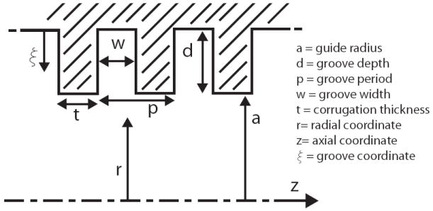
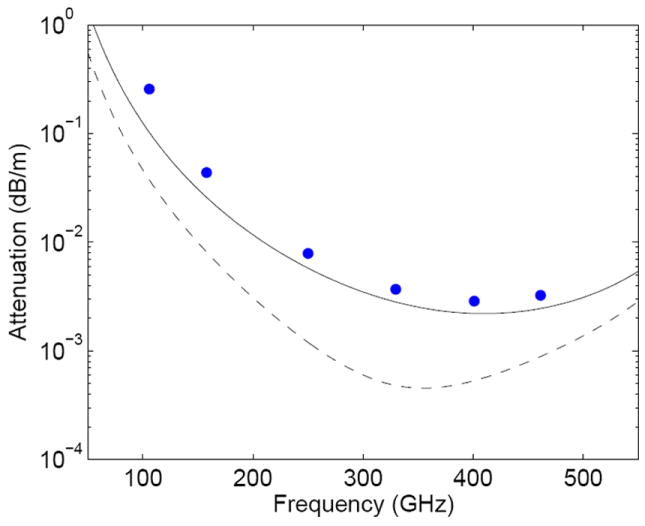
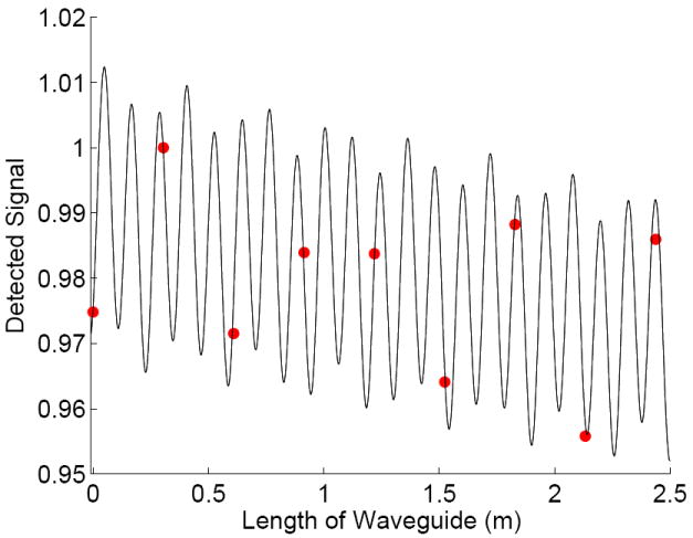
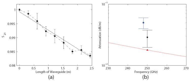
Applications of high-power Terahertz (THz) sources require low-loss transmission lines to minimize loss, prevent overheating and preserve the purity of the transmission mode. Concepts for THz transmission lines are reviewed with special emphasis on overmoded, metallic, corrugated transmission lines. Using the fundamental HE(11) mode, these transmission lines have been successfully implemented with very low-loss at high average power levels on plasma heating experiments and THz dynamic nuclear polarization (DNP) nuclear magnetic resonance (NMR) experiments. Loss in these lines occurs directly, due to ohmic loss in the fundamental mode, and indirectly, due to mode conversion into high order modes whose ohmic loss increases as the square of the mode index. An analytic expression is derived for ohmic loss in the modes of a corrugated, metallic waveguide, including loss on both the waveguide inner surfaces and grooves. Simulations of loss with the numerical code HFSS are in good agreement with the analytic expression. Experimental tests were conducted to determine the loss of the HE(11) mode in a 19 mm diameter, helically-tapped, three meter long brass waveguide with a design frequency of 330 GHz. The measured loss at 250 GHz was 0.029 ± 0.009 dB/m using a vector network analyzer approach and 0.047 ± 0.01 dB/m using a radiometer. The experimental results are in reasonable agreement with theory. These values of loss, amounting to about 1% or less per meter, are acceptable for the DNP NMR application. Loss in a practical transmission line may be much higher than the loss calculated for the HE(11) mode due to mode conversion to higher order modes caused by waveguide imperfections or miter bends.
Figures
References
-
- Woskov PP, Hornstein MK, Temkin RJ. Infrared and Millimeter Waves and 13th International Conference on Terahertz Electronics, The Joint 30th International Conference on; 2005. pp. 563–564.
-
- de Rijk E, Macor A, Hogge JP, Alberti S, Ansermet JP. Rev Sci Instrum. 2011;82(6):066102. - PubMed
-
- Denisov G, Chirkov A, Belousov V, Bogdashov A, Kalynova G, Sobolev D, Rodin Y, Tai E, Ilin V, Kornishin S, Kulygin M, Malygin V, Soluyanova E, Parshin V, Shmelev M. Journal of Infrared, Millimeter and Terahertz Waves. 2011;32(3):343.
-
- Bogdashov A, Belousov V, Chirkov A, Denisov G, Korchagin V, Kornishin S, Tai E. Journal of Infrared, Millimeter and Terahertz Waves. 2011;32(6):823.
Grants and funding
LinkOut - more resources
Full Text Sources
Other Literature Sources
Miscellaneous