

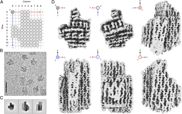
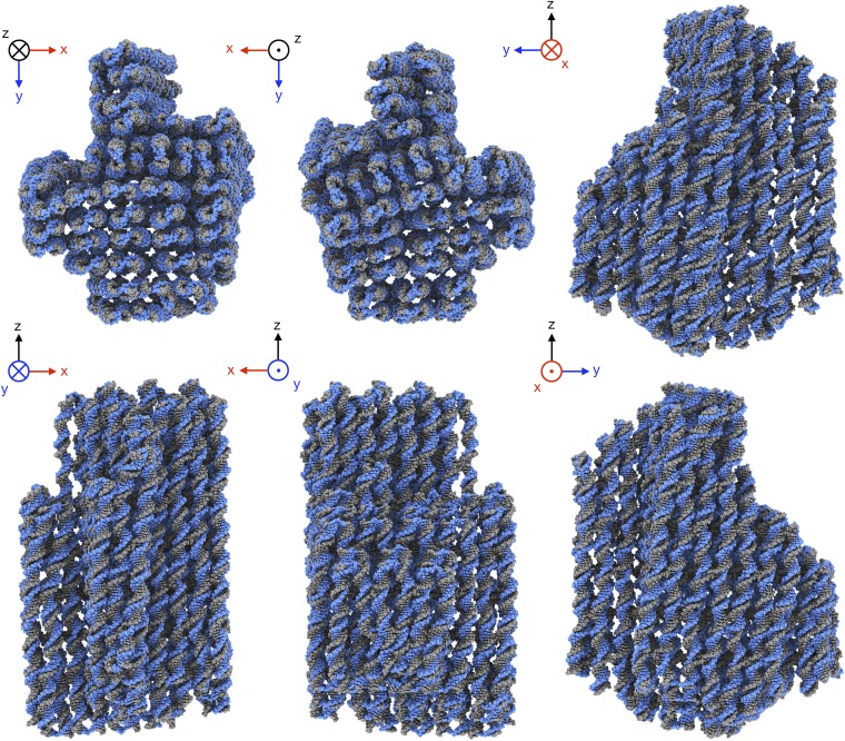
Cryo-EM structure of a 3D DNA-origami object
- PMID: 23169645
- PMCID: PMC3523823
- DOI: 10.1073/pnas.1215713109
Cryo-EM structure of a 3D DNA-origami object
Abstract
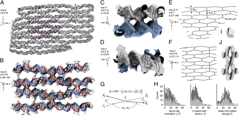
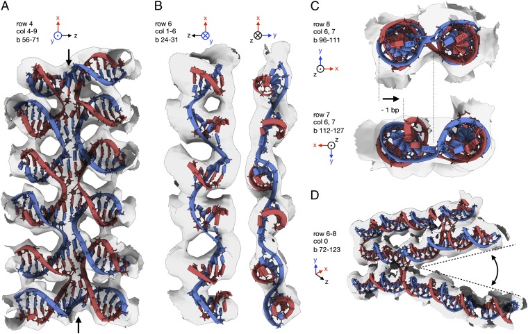
A key goal for nanotechnology is to design synthetic objects that may ultimately achieve functionalities known today only from natural macromolecular complexes. Molecular self-assembly with DNA has shown potential for creating user-defined 3D scaffolds, but the level of attainable positional accuracy has been unclear. Here we report the cryo-EM structure and a full pseudoatomic model of a discrete DNA object that is almost twice the size of a prokaryotic ribosome. The structure provides a variety of stable, previously undescribed DNA topologies for future use in nanotechnology and experimental evidence that discrete 3D DNA scaffolds allow the positioning of user-defined structural motifs with an accuracy that is similar to that observed in natural macromolecules. Thereby, our results indicate an attractive route to fabricate nanoscale devices that achieve complex functionalities by DNA-templated design steered by structural feedback.
Conflict of interest statement
The authors declare no conflict of interest.
Figures
References
-
- Alberts B, et al. Molecular Biology of the Cell. New York: Garland Science; 2002.
-
- Rothemund PWK. Folding DNA to create nanoscale shapes and patterns. Nature. 2006;440(7082):297–302. - PubMed
-
- Shih WM, Quispe JD, Joyce GF. A 1.7-kilobase single-stranded DNA that folds into a nanoscale octahedron. Nature. 2004;427(6975):618–621. - PubMed
Publication types
MeSH terms
Substances
Associated data
- Actions
- Actions
- Actions
Grants and funding
LinkOut - more resources
Full Text Sources
Other Literature Sources
Molecular Biology Databases
