

Electromagnetically-actuated reciprocating pump for high-flow-rate microfluidic applications
- PMID: 23201986
- PMCID: PMC3545557
- DOI: 10.3390/s121013075
Electromagnetically-actuated reciprocating pump for high-flow-rate microfluidic applications
Abstract
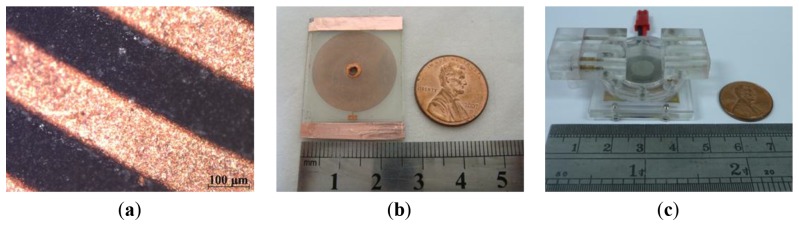
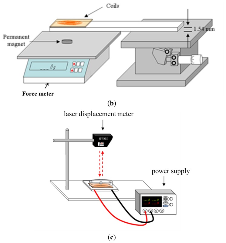
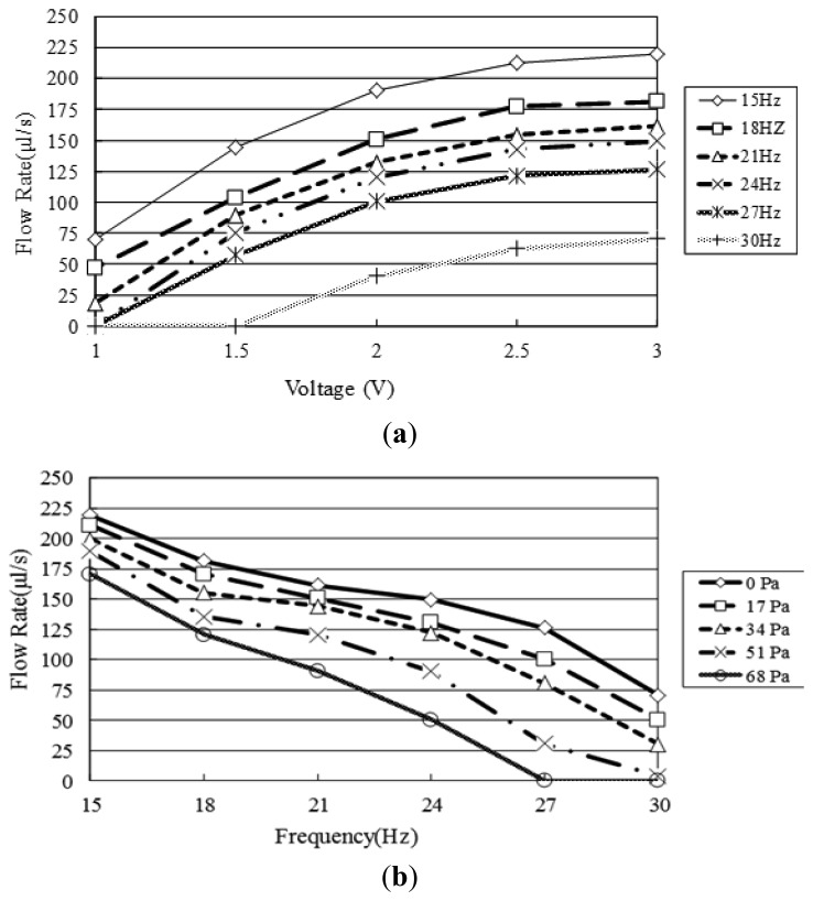
This study presents an electromagnetically-actuated reciprocating pump for high-flow-rate microfluidic applications. The pump comprises four major components, namely a lower glass plate containing a copper microcoil, a middle PMMA plate incorporating a PDMS diaphragm with a surface-mounted magnet, upper PMMA channel plates, and a ball-type check valve located at the channel inlet. When an AC current is passed through the microcoil, an alternating electromagnetic force is established between the coil and the magnet. The resulting bi-directional deflection of the PDMS diaphragm causes the check-valve to open and close; thereby creating a pumping effect. The experimental results show that a coil input current of 0.4 A generates an electromagnetic force of 47 mN and a diaphragm deflection of 108 μm. Given an actuating voltage of 3 V and a driving frequency of 15 Hz, the flow rate is found to be 13.2 mL/min under zero head pressure conditions.
Figures


Similar articles
-
Valveless impedance micropump with integrated magnetic diaphragm.Biomed Microdevices. 2010 Apr;12(2):197-205. doi: 10.1007/s10544-009-9375-8. Biomed Microdevices. 2010. PMID: 19946751
-
Design and analysis of impedance pumps utilizing electromagnetic actuation.Sensors (Basel). 2010;10(4):4040-52. doi: 10.3390/s100404040. Epub 2010 Apr 21. Sensors (Basel). 2010. PMID: 22319340 Free PMC article.
-
A self-priming microfluidic diaphragm pump capable of recirculation fabricated by combining soft lithography and traditional machining.Biotechnol Bioeng. 2004 Feb 5;85(3):359-63. doi: 10.1002/bit.10787. Biotechnol Bioeng. 2004. PMID: 14748092
-
An electromagnetic microvalve for pneumatic control of microfluidic systems.J Lab Autom. 2014 Oct;19(5):444-53. doi: 10.1177/2211068214531760. Epub 2014 Apr 17. J Lab Autom. 2014. PMID: 24742860
-
Surface micromachined electrostatically actuated micro peristaltic pump.Lab Chip. 2004 Oct;4(5):495-501. doi: 10.1039/b403906h. Epub 2004 Sep 14. Lab Chip. 2004. PMID: 15472734
Cited by
-
Shape-Programmable Three-Dimensional Microfluidic Structures.ACS Appl Mater Interfaces. 2022 Apr 6;14(13):15599-15607. doi: 10.1021/acsami.1c24799. Epub 2022 Mar 23. ACS Appl Mater Interfaces. 2022. PMID: 35319180 Free PMC article.
References
-
- Chen L., Lee S., Choo J., Lee E.K. Continuous dynamic flow micropumps for microfluid manipulation. J. Micromech. Microeng. 2008;18 doi: 10.1088/0960-1317/18/1/013001. - DOI
-
- Woias P. Micropumps—Past, progress and futureprospects. Sens. Actuators B Chem. 2005;105:28–38.
-
- Nisar A., Afzulpurkar N., Mahaisavariya B., Tuantranont A. MEMS-based micropumps in drug delivery and biomedical applications. Sens. Actuators B Chem. 2008;130:917–942.
-
- Seibel K., Schöler L., Schäler H., Böhm M. A programmable plannar electroosmotic micropump for lab-on-a-chip applications. J. Micromech. Microeng. 2008;18 doi: 10.1088/0960-1317/18/2/025008. - DOI
-
- Pan T., McDonald S.J., Kai E.M. A magnetically driven PDMS micropump with ball check-valves. J. Micromech. Microeng. 2005;15:1021–1026.
Publication types
MeSH terms
Substances
LinkOut - more resources
Full Text Sources
