. 2013 Mar 11;425(5):914-28.
doi: 10.1016/j.jmb.2012.12.007. Epub 2012 Dec 26.

A "mechanistic" explanation of the multiple helical forms adopted by bacterial flagellar filaments

Affiliations

A "mechanistic" explanation of the multiple helical forms adopted by bacterial flagellar filaments

C R Calladine et al. J Mol Biol. .

Abstract

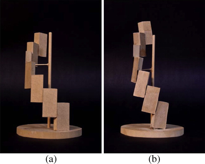
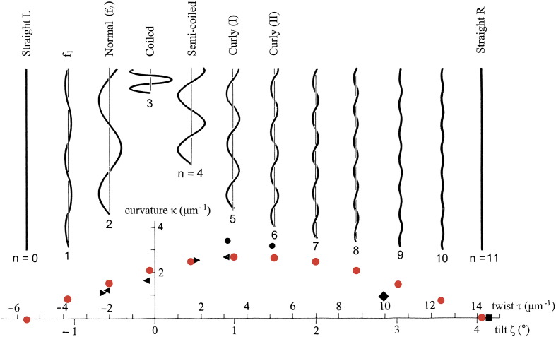
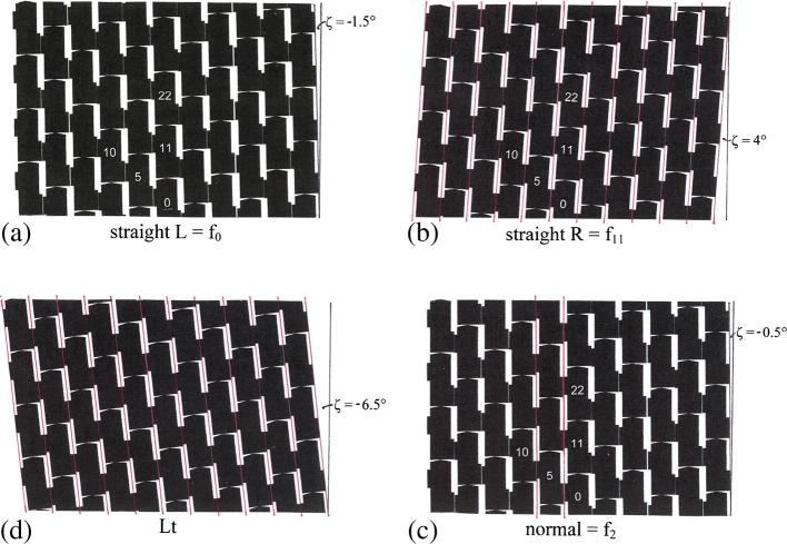
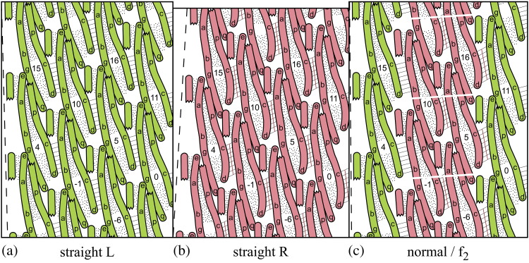
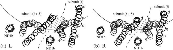
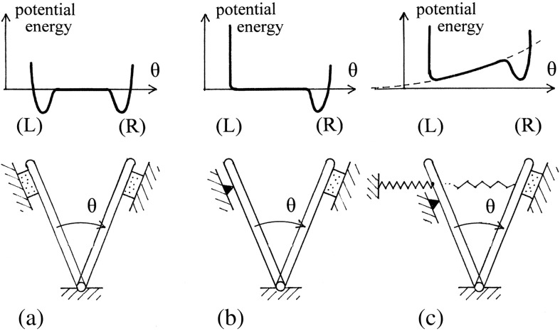
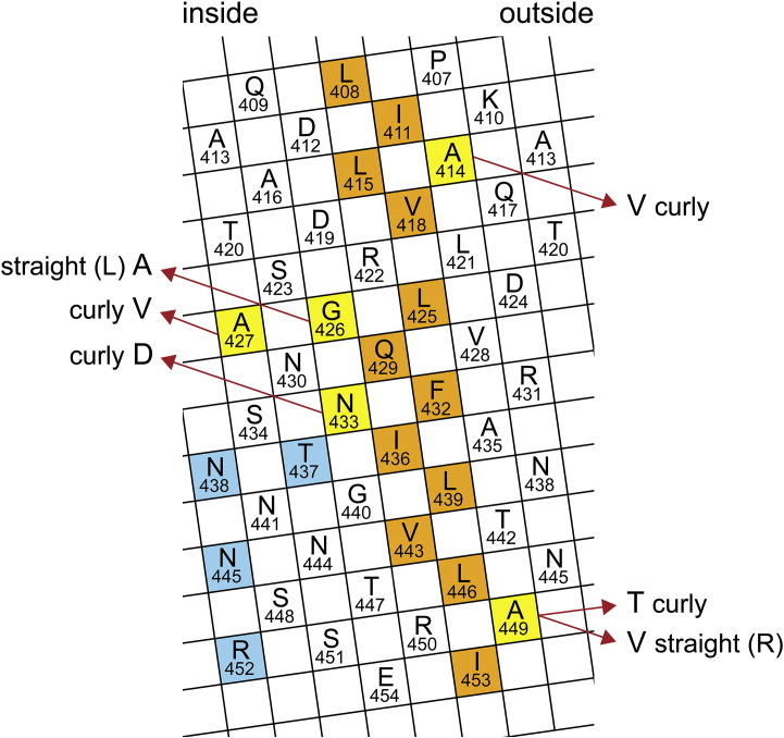
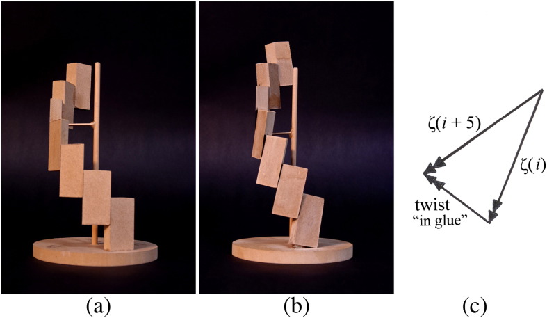
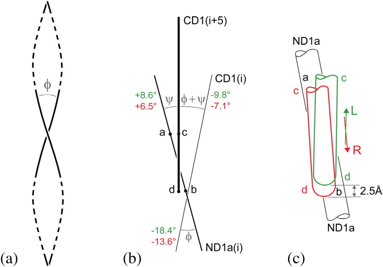
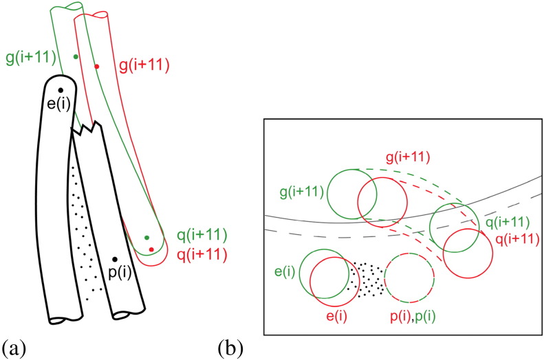
The corkscrew-like flagellar filaments emerging from the surface of bacteria such as Salmonella typhimurium propel the cells toward nutrient and away from repellents. This kind of motility depends upon the ability of the flagellar filaments to adopt a range of distinct helical forms. A filament is typically constructed from ~30,000 identical flagellin molecules, which self-assemble into a tubular structure containing 11 near-longitudinal protofilaments. A "mechanical" model, in which the flagellin building block has the capacity to switch between two principal interfacial states, predicts that the filament can assemble into a "canonical" family of 12 distinct helical forms, each having unique curvature and twist: these include two "extreme" straight forms having left- and right-handed twists, respectively, and 10 intermediate helical forms. Measured shapes of the filaments correspond well with predictions of the model. This report is concerned with two unanswered questions. First, what properties of the flagellin determine which of the 12 discrete forms is preferred? Second, how does the interfacial "switch" work, at a molecular level? Our proposed solution of these problems is based mainly on a detailed examination of differences between the available electron cryo-microscopy structures of the straight L and R filaments, respectively.


Figures

None
Graphical abstract
Fig. 1
Fig. 1
Plot of curvature κ against twist τ for measured helical forms of bacterial flagellar filaments (black points), together with the 12 discrete theoretical points (red), and drawings of the corresponding helical forms, all with contour length 4 μm (after Ref. 13). Values of twist are provided both in units of radian per micrometer and, roughly equivalently, in terms of the angle of tilt, ζ, of the 11-start protofilaments, drawn on a reference cylinder of radius 45 Å. The 12 theoretical, “canonical” states are designated by numbers n = 0, 1…11: n is the number of protofilaments in the shorter, R-type conformation. For the straight L and R filaments, n = 0 and n = 11, respectively; detailed atomic structural data at a resolution of 4 Å are available in Refs. 9 and 10.
Fig. 2
Fig. 2
Unrolled cylindrical surface lattices of flagellar filaments at radius 45 Å. These have been constructed from schematic subunits that allow point contacts on the 11-start lines so as to make protofilaments, and extended contacts on the 5-start lines, by means of a bi-stable connection; however, there are no connections on the 6-start lines. Subunits are numbered in the order of building the filament; a selection of these numbers is shown here. Subunits 0, 11, 22 and 0, 5, 10 lie on typical 11- and 5-start lattice lines, respectively. Subunits 10, 11 and 5, 11 lie on single- and 6-start lattice lines, respectively. The 11 protofilaments may be identified as containing the subunits numbered 0, 1…10. (a) Straight filament with left-handed twist, n = 0: all bi-stable connections are of the L type. (b) Straight filament with right-handed twist, n = 11: all bi-stable connections have sheared by 2.5 Å into the R type and are marked by red lines. (c) Filament n = 2, the normal helical form (see Fig. 1). Here, there are two longitudinal strands of bi-stable 5-start connections of the R type—again marked by red lines—clustered together so as to minimize the overall elastic strain energy of distortion (Ref. 13). (d) Lt straight filament, formed when the polypeptide chain of flagellin is truncated so that the inner tube is not properly constructed. All bi-stable connections are of the R type; the pattern of (b) has been altered by the introduction of a shear dislocation between two adjacent protofilaments. Subunit numbers are not given here, since there is no longer a single-start lattice line passing through all subunits.
Fig. 3
Fig. 3
Portions of cylindrical surface lattices, as in Fig. 2, but now with subunits shown as consisting of three α-helices, representing the α-helical components of the outer-tube moiety of the flagellin subunits. The diagrams are only approximately to scale. The α-helices are shown as sausages of diameter 5 Å and are projected onto the reference cylinder of radius 45 Å. The three α-helices in a subunit are bound together as classical left-handed coiled coils by hydrophobic cores, which are here shown stippled. Within each subunit, helices ND1a (with labels e, a, b, g and q) and CD1 (with labels p, c and d) make a long classical coiled coil, while ND1b makes a short, classical coiled coil with portion ea of ND1a. The distal end of the filament is beyond the top of the picture. For the sake of clarity, the upper end of the long helix CD1 has been cut off, so as not to obscure the 11-start connection between point e at the tip of ND1a of subunit i and point g one-third from the bottom of ND1a of subunit i + 11. Likewise, the lower end of the short α-helix ND1b (not labeled) has been cut off, so as not to obscure the upper end of the bi-stable 5-start connection between the middle third of ND1a of subunit i (portion ab) and the bottom third of CD1 of subunit i + 5 (portion cd): this inter-subunit connection, which makes a right-handed coiled coil, is marked by eight short parallel lines. The broken lines on the left mark the tilt of the 11-start lattice lines. (a and b) Straight L and R filaments, respectively. The differently sheared bi-stable connections can be identified by the orientation of the short parallel lines (cf. Fig. 2). Data from Refs. 9 and 10. Note that the R straight filament is some 1.5% shorter than the L. (c) Part of the n = 2 filament, with two strands of bi-stable connections of type R (marked with red lines) and two protofilaments in the R form. These two protofilaments, of slightly shorter length, will only fit onto the surface of the reference cylinder—or, equivalently, onto a plane as here—if the R-type protofilaments are artificially cut and stretched, as shown. It is the pulling together of the sides of these cuts that imparts curvature to the filament.
Fig. 4
Fig. 4
Axial view of adjacent subunits i and i + 5: adapted from a portion of Fig. 1a of Ref. . Only the three α-helices of the flagellin moiety that builds the outer tube are shown, as spirals passing through the α-carbon atoms. The circular arcs mark the reference cylinder of radius 45 Å. The long α-helix CD1 (cf. Fig. 3)—drawn here with a thicker line—appears more or less straight in this view, with its upper (distal) end at larger radius: locations p, c and d (cf. Fig. 3) are marked. The α-helix ND1a “wraps around” CD1 in this view: its upper end is at larger radius, and points e, a, b and q are marked. Helix ND1b, which is practically axial, appears as a small circle in this view. The bi-stable interface between ab and cd is marked by five lines, somewhat as in Fig. 3: observe that portion ab of ND1a appears to be straight in this view. (a) L filament, (b) R filament.
Fig. 5
Fig. 5
A physical analog of a mechanically bi-stable feature: the swinging gate. (a) A swinging gate with a magnetic catch (here, a stippled rectangle) at each end of its travel: the upper diagram shows a schematic plot of the total energy of the system, with two potential wells. (b) As (a), but with the magnetic catch at one end replaced by a simple stop: the arrangement is now mono-stable. (c) As (b), but with the addition of a restraining linear elastic spring that would be relaxed if the gate could swing further to the left, beyond the stop. The potential function is now the sum of two terms: a quadratic one for the elastic spring and the previous one (b) for the magnetic catch. The stiffness of the spring has here been adjusted so as to make the device bi-stable, as witnessed by the potential function.
Fig. 6
Fig. 6
Cylindrical surface lattice of α-helix CD1 for wild-type protein, after Kanto et al. Here, the amino acids are represented by 5-Å squares, labeled appropriately. The diagram may be cut out and rolled into a cylinder of diameter 11 Å, ready to engage with neighboring α-helices with center–center spacing of 11 Å: note that, for this purpose, some squares are shown repeating on the edges. Residues forming the hydrophobic stripe, which connects with ND1a to make a classical left-handed supercoil, are colored orange. Six single-amino-acid substitutions that cause the flagellin to construct different helical forms have been marked.
Fig. 7
Fig. 7
Physical models of a 5-spiral. (a) The blocklike subunits are vertical, that is, parallel with the axis of the helix. (b) The blocks are now tilted to the right by 10°, which requires the glued joints to be “twisted” by some 5°. The overall height is larger than in (a): the compensating shearing action of the “switches” between blocks has not been modeled here. (c) Vector diagram for the 10° rotation of two adjacent blocks, in a plane perpendicular to the vertical axes of (a) and (b). These vectors of “small rotation” are normal to the respective blocks, and their difference gives the “twist” of the glued joints in (b).
Fig. 8
Fig. 8
(a) Centerlines of two α-helices making a classical coiled coil and defining the crossing angle φ of the supercoil. Here, the coiled coil has left-handed twist along its axis, and by convention, φ has a negative value. Not to scale: the angle φ shown here is some 50% larger than our largest computed values. See Table 1 for the method of calculation of crossing angle. (b) Schematic view of three α-helices, looking from left to right in Fig. 3 and showing the crossing angles between them. Nearest to the viewer, and shown thickest, is α-helix CD1 of subunit i + 5: its lower one-third, cd, forms a right-handed coiled coil (ψ) with the central portion ab of ND1a of subunit i. Here [cf. (a)], the α-helices are shown straight: it is the crossing angles that are of primary interest. The crossing angle between ND1a and CD1, both of subunit i, is designated φ. Values of φ and ψ are given in green for the straight L structure (Ref. 10) and in red for the straight R structure (Ref. 9). Of special interest is the twist angle (φ + ψ) (“in the glue” of Fig. 7) between CD1 (i + 5) and CD1(i) and, in particular, the change in its value in the L-to-R transition (see Table 1). (c) Close-up view of the switch connection ab/cd of (b). The portions cd shown in green and red correspond to the straight L and R structures, respectively: note that the switch connection is such that the change in angle ψ is directly related to the vertical shearing movement of 2.5 Å within the switch. Data from Refs. 9 and 10.
Fig. 9
Fig. 9
Schematic local close-up views of the 11-start interconnections between portions e and p of subunit i and portions g and q of subunit i + 11. In (a), close-ups of a single connection in the straight L and R conformations (from the same viewpoint as for Fig. 3) have been superposed so that the relative motion of subunit i + 11 to subunit i may be seen. In this picture, the lower portion of α-helix CD1 of subunit i + 11 has been shown green (L) and red (R); the relative vertical movement (which makes the R protofilament significantly shorter than the L) has been exaggerated by a factor of 2, for clarity. In (b), an axial view (at a larger scale: 1.5 ×) of the same feature: the circular arcs are at radius 45 Å, and the pictures have been superposed on portion p. Here, we can see that the relative movement p/q is mainly radial, while at e/g the relative movement is mainly circumferential. Data from Refs. 9 and 10.

Similar articles

Cited by

References

    1. Asakura S. Polymerization of flagellin and polymorphism of flagella. Adv. Biophys. J. 1970;1:99–155. - PubMed
    1. Berg H.C., Anderson R.A. Bacteria swim by rotating their flagellar filaments. Nature. 1973;245:380–382. - PubMed
    1. Larsen S.H., Reader R.W., Kort E.N., Tso W.W., Adler J. Change in direction of flagellar rotation is the basis of the chemotactic response in Escherichia coli. Nature. 1974;249:74–77. - PubMed
    1. Macnab R.M., Ornston M.K. Normal-to-curly flagellar transitions and their role in bacterial tumbling: stabilization of an alternative quaternary structure by mechanical force. J. Mol. Biol. 1977;112:1–30. - PubMed
    1. Turner L., Ryu W.S., Berg H.D. Real-time imaging of fluorescent flagellar filaments. J. Bacteriol. 2000;182:2793–2801. - PMC - PubMed

Publication types

LinkOut - more resources