. 2012;7(12):e52505.
doi: 10.1371/journal.pone.0052505. Epub 2012 Dec 27.

Binding pocket optimization by computational protein design

Affiliations

Binding pocket optimization by computational protein design

Christoph Malisi et al. PLoS One. 2012.

Abstract

Engineering specific interactions between proteins and small molecules is extremely useful for biological studies, as these interactions are essential for molecular recognition. Furthermore, many biotechnological applications are made possible by such an engineering approach, ranging from biosensors to the design of custom enzyme catalysts. Here, we present a novel method for the computational design of protein-small ligand binding named PocketOptimizer. The program can be used to modify protein binding pocket residues to improve or establish binding of a small molecule. It is a modular pipeline based on a number of customizable molecular modeling tools to predict mutations that alter the affinity of a target protein to its ligand. At its heart it uses a receptor-ligand scoring function to estimate the binding free energy between protein and ligand. We compiled a benchmark set that we used to systematically assess the performance of our method. It consists of proteins for which mutational variants with different binding affinities for their ligands and experimentally determined structures exist. Within this test set PocketOptimizer correctly predicts the mutant with the higher affinity in about 69% of the cases. A detailed analysis of the results reveals that the strengths of PocketOptimizer lie in the correct introduction of stabilizing hydrogen bonds to the ligand, as well as in the improved geometric complemetarity between ligand and binding pocket. Apart from the novel method for binding pocket design we also introduce a much needed benchmark data set for the comparison of affinities of mutant binding pockets, and that we use to asses programs for in silico design of ligand binding.


Conflict of interest statement

Competing Interests: The authors have declared that no competing interests exist.

Figures

Figure 1
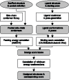
Figure 1. Workflow of PocketOptimizer.
The input specific for a design is depicted in circles, parts of the pipeline are shown in pointed rectangles, and output components in rounded rectangles. The output is stored in standard file formats (SDF and PDB for structural data, csv for energy tables). This allows the easy replacement of a component with another that solves the same task (e.g. replacing the binding score function).
Figure 2
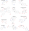
Figure 2. Two-dimensional structures of benchmark set ligands.
The ligands of the test cases of our benchmark sets. See Table 1 for which ligand belongs to which test case.
Figure 3
Figure 3. Differences of the ligand poses and pocket side chains in the benchmark designs compared to the crystal structures.
The upper graph shows the average RMSDs and standard deviation between the ligand pose in the designs and in the crystal structures. The lower graph shows the average RMSD and standard deviation between the binding pocket side chain heavy atoms of designs and the corresponding crystal structure. The RMSDs are calculated after superimposing the structures using the backbone to make sure that the differences come from pocket/ligand pose differences only. RMSD from PocketOptimizer CADDSuite score designs are plotted in blue, from PocketOptimizer vina designs in green, and from Rosetta designs in red. Each point marks the average RMSD for all designs of a test case usign one score. The number of designs that contribute to a value depends on the number of mutations with a crystal structure, it is the square of this number (because each structure is used as a design scaffold for each mutation). Test cases are: CA: Carbonic anhydrase II, ABP D7r4 amine binding protein, ER: Estrogen receptor formula image, HP: HIV-1 protease, KI: Ketosteroid isomerase, L: Lectin, MS: Methylglyoxal synthase, N1: Neuroaminidase test 1, N2: Neuroaminidase test 2, PNP: Purine nucleoside phosphorylase, S1: Streptavidin test 1, S2: Streptavidin test 2, TS: Thymidylate synthase, T: Trypsin.
Figure 4
Figure 4. Comparison of the energy scores versus the affinities of the mutations show how well the programs reproduce the differences.
For each test case with more than two mutations, we plotted the top binding scores of CADDSuite, Vina, and Rosetta designs for each mutation on each scaffold structure together with the logarithm of the affinity. Here we show plots for Carbonic anhydrase II, HIV-1 protease, and Streptavidin test 1. All other plots are shown in Information S1. Values are scaled to fit in the same range. Shown on the x-axis of a plot are the mutants in order of affinity to the ligand (the leftmost has the lowest affinity, compare Table 1 for the actual values). The y-axis measures predicted binding scores for the designs, and the log affinities, scaled between 0 and 1. Both are proportional to the binding free energy, and can therefore be compared when scaled to the same range. The lowest predicted binding score or log affinity is set to 0, the highest respective value to 1. Each plot contains a line for the affinity logarithm (solid, black no marker). This line represents the goal, if a method predicts binding well, the binding score lines should closely follow the log affinity line. The other markers and lines show the scaled predicted binding scores. One line represents the designs calculated for all available mutants, calculated by using one crystal structure as the scaffold. (Crystal structure 1: dashed, blue, circle markers; structure 2: red, dotted, square markers; structure 3: green, dash-dot pattern, diamond markers; structure 4: cyan, two dashes one dot pattern, star markers). We chose to use lines for representation, because this makes it easy to visually compare the shape of the black log affinity line to the lines representing the design binding scores. Each row has plots for one test case, in parentheses the order of scaffold structures is listed: CA: Carbonic anhydrase II (1ydb, 1yda, 1ydd), HP: HIV-1 protease (1met, 1meu, 1mes), S1: Streptavidin test 1 (1swe, 1n43).

References

    1. Vallée-Bélisle A, Plaxco KW (2010) Structure-switching biosensors: inspired by nature. Curr Opin Struct Biol 20: 518–526. - PMC - PubMed
    1. Benson DE, Wisz MS, Hellinga HW (2000) Rational design of nascent metalloenzymes. Proc Natl Acad Sci U S A 97: 6292–6297. - PMC - PubMed
    1. Bolon DN, Mayo SL (2001) Enzyme-like proteins by computational design. Proc Natl Acad Sci U S A 98: 14274–14279. - PMC - PubMed
    1. Röthlisberger D, Khersonsky O, Wollacott AM, Jiang L, DeChancie J, et al. (2008) Kemp elimination catalysts by computational enzyme design. Nature 453: 190–195. - PubMed
    1. Korendovych IV, Kulp DW, Wu Y, Cheng H, Roder H, et al. (2011) Design of a switchable eliminase. Proc Natl Acad Sci U S A 108: 6823–7. - PMC - PubMed

Publication types