. 2013 Jan 9;33(2):776-89.
doi: 10.1523/JNEUROSCI.1784-12.2013.

Influence of core auditory cortical areas on acoustically evoked activity in contralateral primary auditory cortex

Affiliations

Influence of core auditory cortical areas on acoustically evoked activity in contralateral primary auditory cortex

Andres Carrasco et al. J Neurosci. .

Abstract

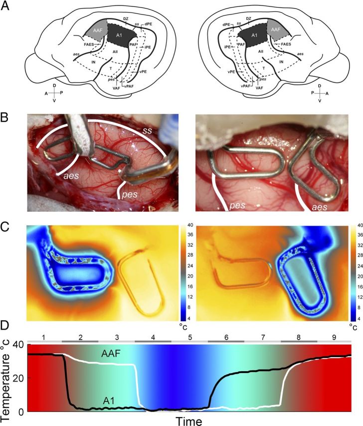
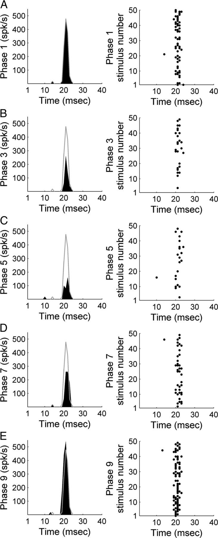
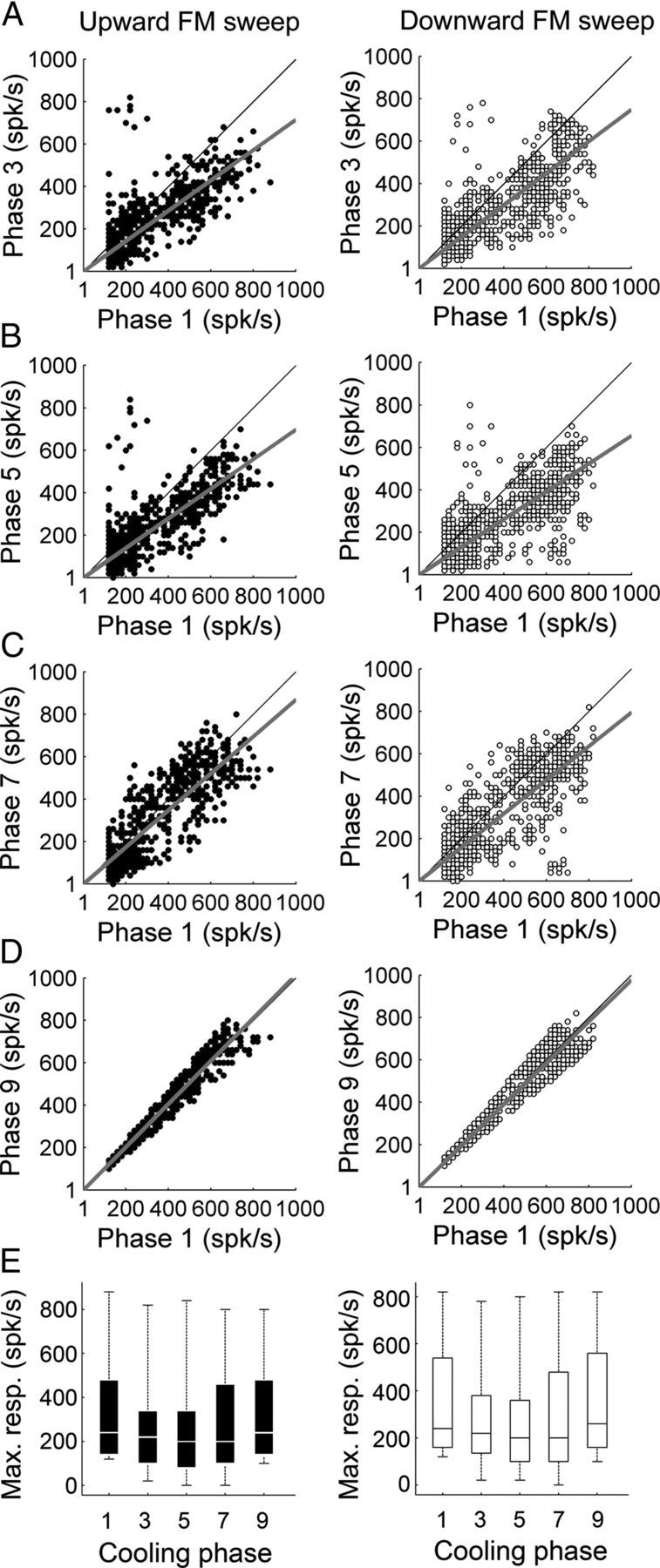
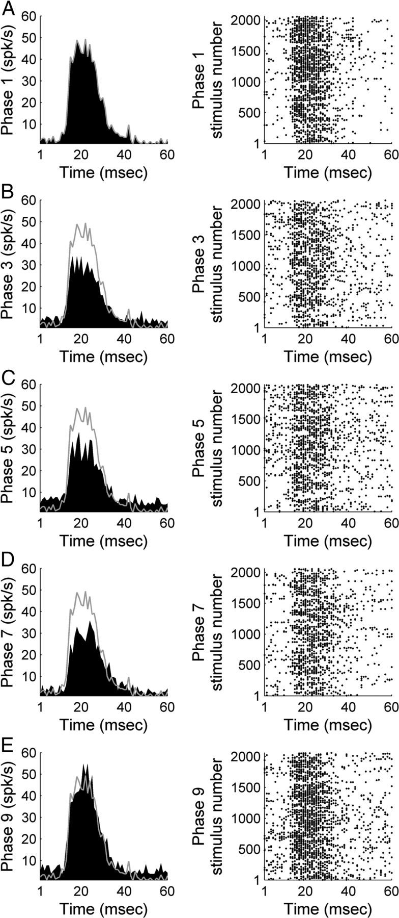
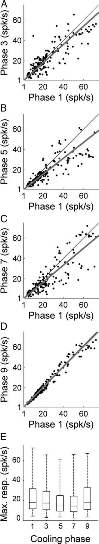
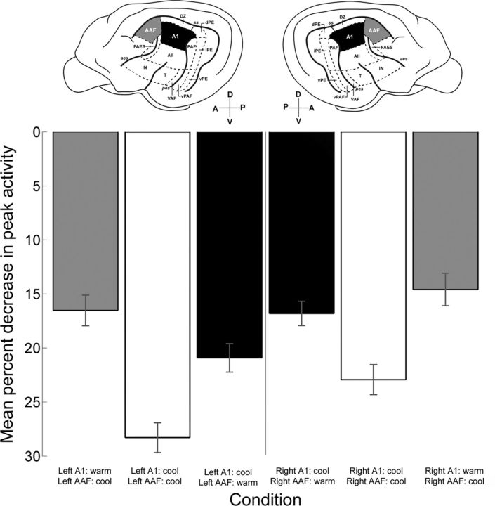
In contrast to numerous studies of transcallosal communication in visual and somatosensory cortices, the functional properties of interhemispheric connections between auditory cortical fields have not been widely scrutinized. Therefore, the purpose of the present investigation was to measure the magnitude and type (inhibitory/excitatory) of modulatory properties of core auditory fields on contralateral primary auditory cortex (A1) activity. We combined single-unit neuronal recordings with reversible cooling deactivation techniques to measure variations in contralateral A1 response levels during A1, anterior auditory field (AAF), or simultaneous A1 and AAF neuronal discharge suppression epochs in cat auditory cortex. Cortical activity was evoked by presentation of pure tones, noise bursts, and frequency-modulated (FM) sweeps before, during, and after cortical deactivation periods. Comparisons of neuronal response changes before and during neuronal silencing revealed three major findings. First, deactivation of A1 and AAF-induced significant peak response reductions in contralateral A1 activity during simple (tonal) and complex (noise bursts and FM sweeps) acoustic exposure. Second, decreases in A1 neuronal activity appear to be in agreement with anatomical laminar termination patterns emanating from contralateral auditory cortex fields. Third, modulatory properties of core auditory areas lack hemispheric lateralization. These findings demonstrate that during periods of acoustic exposure, callosal projections emanating from core auditory areas modulate A1 neuronal activity via excitatory inputs.


Figures

Figure 1.
Figure 1.
A, Schematic illustration of the left and right hemispheres of the cat cerebrum showing the 13 areas of cat auditory cortex. A1 is highlighted in black and AAF is shown in gray. B, Representative examples of reversible cooling loop placement in left (left side) and right (right side) hemispheres from two implanted animals. temperature changes during A1 (left) and AAF (right) cooling deactivation epochs. C, Temperature changes were recorded from a single animal during cooling loop. Notice that deactivation did not extend to adjacent cortical fields. D, Temperature changes recorded at A1 and AAF cooling loops of an implanted animal during a complete cooling deactivation cycle. Numbers on top indicate the phase of the cycle, with even numbers representing transitional temperature periods and odd numbers showing constant temperature epochs. Note that colors are presented as a guide of cortical temperature changes during cooling deactivation and are not associated with a color bar. A1, primary auditory cortex; AII, second auditory cortex; AAF, anterior auditory field; dPE, dorsal posterior ectosylvian area; DZ, dorsal zone of auditory cortex; FAES, auditory field of the anterior ectosylvian sulcus; IN, insular region; iPE, intermediate posterior ectosylvian area; PAF, posterior auditory field; T, temporal region; VAF, ventral auditory field; vPAF, ventral posterior auditory field; vPE, ventral posterior ectosylvian area. The sulci are indicated by italics: aes, anterior ectosylvian sulcus; ss, suprasylvian sulcus; pes, posterior ectosylvian sulcus. D, dorsal; A, anterior; P, posterior; V, ventral.
Figure 2.
Figure 2.
Left, Photomicrograph of a Nissl-stained coronal section showing A1 laminar organization. Layers are labeled with roman numerals and boundaries are marked with oblique lines. Center, Photomicrograph of a Nissl-stained coronal section highlighting a recording electrode track. Line illustrates putative location of a 12-channel recording electrode. Cortical layers are labeled with roman numerals and marked with oblique lines. Right, Schematic illustration of recording electrode channel number and spacing.
Figure 3.
Figure 3.
Representative example of A1 response strength during white noise burst exposure before, during, and after contralateral deactivation of core auditory areas. PSTH and corresponding raster example of a single-unit in A1 before contralateral cooling (phase 1, A), during contralateral A1 cooling (phase 3, B), during simultaneous contralateral A1 and AAF cooling (phase 5, C), during contralateral AAF cooling (phase 7, D), and after contralateral cooling periods (phase 9, E). Gray lines across left column delineate warm (top, phase 1) response level to facilitate comparisons across cooling conditions.
Figure 4.
Figure 4.
Comparison of A1 peak response strength during white noise burst exposure before, during, and after contralateral deactivation of core auditory areas. A, Peak response strength of A1 single units before (abscissa) and during (ordinate) contralateral A1 cooling (phase 3). B, Peak response strength of A1 single units before (abscissa) and during (ordinate) simultaneous A1 and AAF contralateral deactivation (phase 5). C, Peak response strength of A1 single units before (abscissa) and during (ordinate) contralateral AAF deactivation (phase 7). D, Peak response strength of A1 single units before (abscissa) and after (ordinate) contralateral deactivation (phase 9). E, Group data are presented in box plots where horizontal box lines illustrate lower quartile, median, and upper quartile values and whiskers extend to most extreme data values. Statistical significance decreases from baseline (phase 1) measures (n = 131 single units, Kruskal–Wallis tests, p < 0.05, followed by post hoc Tukey–Kramer corrections) were identified in phase 5. Least-square regression lines are plotted in gray (A–D), and cooling phases are explained in Figure 1D.
Figure 5.
Figure 5.
Representative example of A1 activity during exposure to 50 upward FM sweeps (2–16 kHz range; CF 7.34 kHz) before, during, and after contralateral deactivation of core auditory areas. PSTH and corresponding raster example of a single unit in A1 before contralateral cooling (phase 1, A), during contralateral A1 cooling (phase 3, B), during simultaneous contralateral A1 and AAF cooling (phase 5, C), during contralateral AAF cooling (phase 7, D), and during the contralateral rewarm stage (phase 9, E). Gray lines across left column delineate warm (top, phase 1) response level to facilitate comparisons across cooling conditions.
Figure 6.
Figure 6.
Comparison of A1 peak response strength during upward and downward FM sweep exposure before, during, and after contralateral deactivation of core auditory areas. A, Peak response strength of A1 single units before (abscissa) and during (ordinate) contralateral A1 cooling (phase 3). B, Peak response strength of A1 single units before (abscissa) and during (ordinate) simultaneous A1 and AAF contralateral deactivation (phase 5). C, Peak response strength of A1 single units before (abscissa) and during (ordinate) contralateral AAF deactivation (phase 7). D, Peak response strength of A1 single units before (abscissa) and after (ordinate) contralateral deactivation (phase 9). E, Group data are presented in box plot form in which horizontal box lines illustrate lower quartile, median, and upper quartile values and whiskers extend to most extreme data values. Statistical significance decreases from baseline (phase 1) peak activity measures (upward FM sweeps, n (single units) = 223; downward FM sweeps, n (single units) = 230, Kruskal–Wallis tests, p < 0.05, followed by post hoc Tukey–Kramer corrections) were identified in phases 3, 5, and 7 in both acoustic conditions. Least-square regression lines are plotted in gray (A–D), and cooling phases are explained in Figure 1D.
Figure 7.
Figure 7.
Representative example of A1 activity during exposure to pure tones of various frequencies and amplitudes before, during, and after contralateral deactivation of core auditory areas. PSTH and corresponding raster example of a single unit in A1 (CF: 4 kHz) before contralateral cooling (phase 1, A), during contralateral A1 cooling (phase 3, B), during simultaneous contralateral A1 and AAF cooling (phase 5, C), during contralateral AAF cooling (phase 7, D), and during contralateral rewarm periods (phase 9, E). Gray lines across left column delineate warm (top, phase 1) response level to facilitate comparisons across cooling conditions.
Figure 8.
Figure 8.
Comparison of A1 peak response strength during pure tone exposure before, during, and after contralateral deactivation of core auditory areas. A, Peak response strength of A1 single units before (abscissa) and during (ordinate) contralateral A1 cooling (phase 3). B, Peak response strength of A1 single units before (abscissa) and during (ordinate) simultaneous A1 and AAF contralateral deactivation (phase 5). C, Peak response strength of A1 single units before (abscissa) and during (ordinate) contralateral AAF deactivation (phase 7). D, Peak response strength of A1 single units before (abscissa) and after (ordinate) contralateral deactivation (phase 9). E, Group data are presented in box plots where horizontal box lines illustrate lower quartile, median, and upper quartile values and whiskers extend to lower and upper limits of the most extreme data values. Statistical significance decreases from baseline (phase 1) levels (n = 174 single units, Kruskal–Wallis tests, p < 0.05, followed by post hoc Tukey–Kramer corrections) were identified in phases 5 and 7. Least-square regression lines are plotted in gray (A–D), and cooling phases are explained in Figure 1D.
Figure 9.
Figure 9.
Representative effect of cooling deactivation on receptive field properties. Panels from top to bottom illustrate receptive field features before cooling deactivation (phase 1), during contralateral A1 deactivation (phase 3), during simultaneous contralateral A1 and AAF deactivation (phase 5), during contralateral AAF deactivation alone (phase 7), and after cooling deactivation (phase 9, rewarm phase). Receptive field borders before cooling (white trace) are illustrated across all phases for comparative purposes. Note the lack of bandwidth variance between warm, cool, and rewarm epochs. Corresponding PSTH activity is presented in Figure 4A.
Figure 10.
Figure 10.
A, Average neuronal response threshold levels of A1 single units before cooling deactivation (phase 1), during contralateral A1 deactivation (phase 3), during simultaneous A1 and AAF deactivation (phase 5), during AAF deactivation alone (phase 7), and subsequent to cooling periods (phase 9, rewarm phase). Statistical significance increases from baseline levels (phase 1) were identified in phases 5 and 7 (n = 174 single units, Kruskal–Wallis tests, *p < 0.05, followed by post hoc Tukey–Kramer corrections). Error bars indicate SE. Bar colors represent cooling stages: red, warm and rewarm epochs; light blue, single field cooling deactivation; dark blue, combined A1 and AAF cooling deactivation). B, Group analysis of A1 receptive field bandwidths before, during, and after contralateral cooling deactivation epochs. Bandwidth measures are illustrated at four intensities above neuronal threshold. Note the lack of variation across conditions. Error bars indicate SE, n = 174.
Figure 11.
Figure 11.
Mean percentage change in peak response strength across A1 cortical thickness before, during, and after contralateral A1 and/or AAF cooling deactivation. A, Number (n = 758) of A1 single units measured during contralateral deactivation with respect to cortical depth. B, Mean percentage change in peak response strength of A1 neurons across laminae during contralateral A1 deactivation. C, Mean percentage change in peak response strength of A1 neurons across laminae during the simultaneous cooling deactivation of contralateral A1 and AAF. D, Mean percentage change in peak response strength of A1 neurons across laminae during contralateral AAF cooling deactivation. Numbers on the ordinate represent electrode number (150 μm apart) with 1 representing the deepest cortical electrode position (approximately layers V–VI) and 12 signifying the most superficial location (approximately layers I–II). Histograms (B–D) show mean ± SEM. The only comparison across laminar groups that revealed statistical significant levels (Kruskal–Wallis tests, p < 0.05, followed by post hoc Tukey–Kramer corrections) occurred between D and M groups during A1 deactivation (B). S, superficial layers; M, mid layers; D, deep layers. Note that the number of single units totals the sum of 131 (noise), 174 (pure tones), and 453 (up and down FM sweeps) A1 single-unit recordings. Error bars indicate SE.
Figure 12.
Figure 12.
Trends in peak response change across A1 laminae during contralateral A1 and/or AAF cooling deactivation. Note that the simultaneous deactivation of A1 and AAF resulted in higher levels of response change than during periods of A1 or AAF cooling deactivation alone. Also, notice that in two of the three conditions investigated middle layers revealed a smaller degree of response change than those observed in deep and superficial laminae.
Figure 13.
Figure 13.
Comparison of variations in A1 peak response across hemispheres. Mean percentage decreases in A1 peak activity during cooling deactivation of contralateral A1 (black bars), simultaneous contralateral A1 and AAF (white bars), and contralateral AAF (gray bars). The left side of the figure illustrates recordings conducted in right hemisphere A1, and the right side of the figure represents recordings from left hemisphere A1. Histograms show mean ± SEM. Left hemisphere recordings: n = 324 (73 noise bursts; 53, pure tones; 198 FM sweeps), right hemisphere recordings: n = 434 (101 noise bursts; 78, pure tones; 434 FM sweeps). Data analyses failed to reveal statistical significant variations between hemispheres (Kruskal–Wallis tests, p < 0.05, followed by post hoc Tukey–Kramer corrections).

Similar articles

Cited by

References

    1. Abel PL, O'Brien BJ, Olavarria JF. Organization of callosal linkages in visual area V2 of macaque monkey. J Comp Neurol. 2000;428:278–293. - PubMed
    1. Adams JC, Warr WB. Origins of axons in the cat's acoustic striae determined by injection of horseradish peroxidase into severed tracts. J Comp Neurol. 1976;170:107–121. - PubMed
    1. Adey WR. Biophysical and metabolic bases of cooling effects on cortical membrane potentials in the cat. Exp Neurol. 1974;42:113–140. - PubMed
    1. Aitkin LM, Kudo M, Irvine DR. Connections of the primary auditory cortex in the common marmoset, Callithrix jacchus jacchus. J Comp Neurol. 1988;269:235–248. - PubMed
    1. Alibardi L. Cytology, synaptology and immunocytochemistry of commissural neurons and their putative axonal terminals in the dorsal cochlear nucleus of the rat. Ann Anat. 2000;182:207–220. - PubMed

Publication types

LinkOut - more resources