

A flexible sensor technology for the distributed measurement of interaction pressure
- PMID: 23322104
- PMCID: PMC3574719
- DOI: 10.3390/s130101021
A flexible sensor technology for the distributed measurement of interaction pressure
Abstract
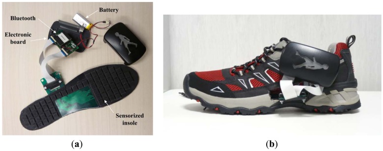
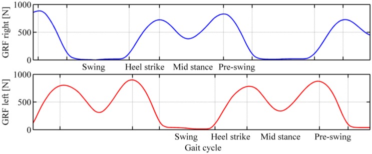
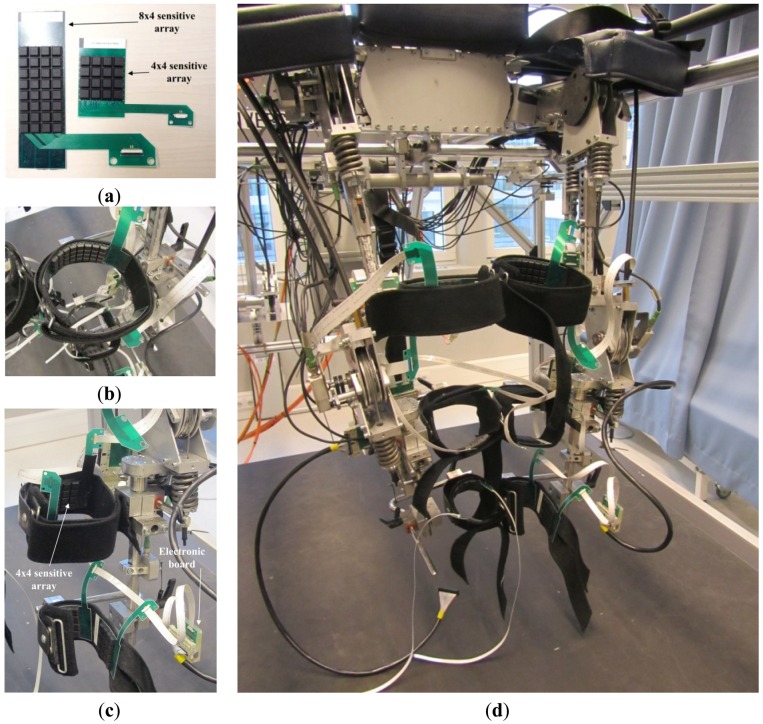
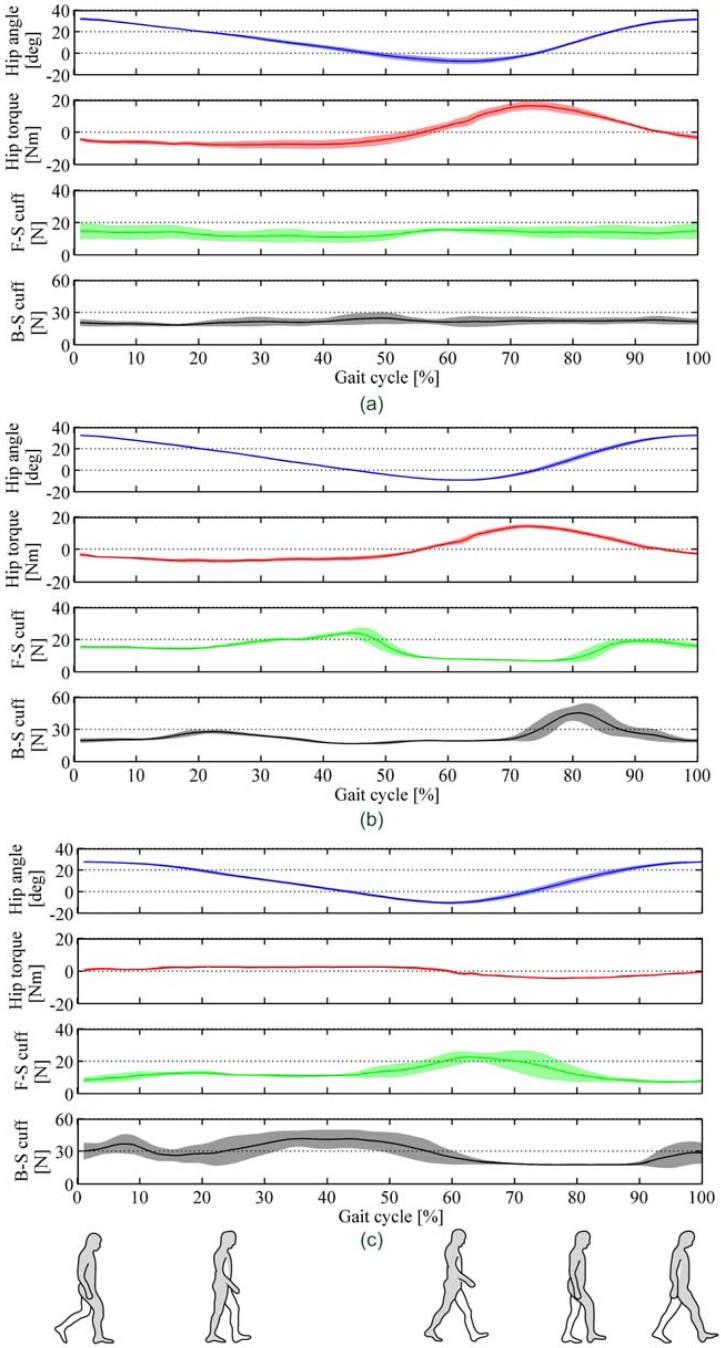
We present a sensor technology for the measure of the physical human-robot interaction pressure developed in the last years at Scuola Superiore Sant'Anna. The system is composed of flexible matrices of opto-electronic sensors covered by a soft silicone cover. This sensory system is completely modular and scalable, allowing one to cover areas of any sizes and shapes, and to measure different pressure ranges. In this work we present the main application areas for this technology. A first generation of the system was used to monitor human-robot interaction in upper- (NEUROExos; Scuola Superiore Sant'Anna) and lower-limb (LOPES; University of Twente) exoskeletons for rehabilitation. A second generation, with increased resolution and wireless connection, was used to develop a pressure-sensitive foot insole and an improved human-robot interaction measurement systems. The experimental characterization of the latter system along with its validation on three healthy subjects is presented here for the first time. A perspective on future uses and development of the technology is finally drafted.
Figures


Similar articles
-
A wireless flexible sensorized insole for gait analysis.Sensors (Basel). 2014 Jan 9;14(1):1073-93. doi: 10.3390/s140101073. Sensors (Basel). 2014. PMID: 24412902 Free PMC article.
-
Sensing pressure distribution on a lower-limb exoskeleton physical human-machine interface.Sensors (Basel). 2011;11(1):207-27. doi: 10.3390/s110100207. Epub 2010 Dec 28. Sensors (Basel). 2011. PMID: 22346574 Free PMC article.
-
Soft artificial tactile sensors for the measurement of human-robot interaction in the rehabilitation of the lower limb.Annu Int Conf IEEE Eng Med Biol Soc. 2010;2010:1279-82. doi: 10.1109/IEMBS.2010.5626409. Annu Int Conf IEEE Eng Med Biol Soc. 2010. PMID: 21095918
-
A review of lower extremity assistive robotic exoskeletons in rehabilitation therapy.Crit Rev Biomed Eng. 2013;41(4-5):343-63. doi: 10.1615/critrevbiomedeng.2014010453. Crit Rev Biomed Eng. 2013. PMID: 24941413 Review.
-
Exoskeleton robots for upper-limb rehabilitation: state of the art and future prospects.Med Eng Phys. 2012 Apr;34(3):261-8. doi: 10.1016/j.medengphy.2011.10.004. Epub 2011 Nov 2. Med Eng Phys. 2012. PMID: 22051085 Review.
Cited by
-
Assistive technology using integrated flexible sensor and virtual alarm unit for blood leakage detection during dialysis therapy.Healthc Technol Lett. 2016 Oct 7;3(4):290-296. doi: 10.1049/htl.2016.0051. eCollection 2016 Dec. Healthc Technol Lett. 2016. PMID: 30800319 Free PMC article.
-
Development of the Ultralight Hybrid Pneumatic Artificial Muscle: Modelling and optimization.PLoS One. 2021 Apr 22;16(4):e0250325. doi: 10.1371/journal.pone.0250325. eCollection 2021. PLoS One. 2021. PMID: 33886654 Free PMC article.
-
Digitized Construction of Iontronic Pressure Sensor with Self-Defined Configuration and Widely Regulated Performance.Sensors (Basel). 2022 Aug 16;22(16):6136. doi: 10.3390/s22166136. Sensors (Basel). 2022. PMID: 36015893 Free PMC article.
-
Vision-Based Pose Estimation for Robot-Mediated Hand Telerehabilitation.Sensors (Basel). 2016 Feb 5;16(2):208. doi: 10.3390/s16020208. Sensors (Basel). 2016. PMID: 26861333 Free PMC article.
-
Characterization and Evaluation of Human-Exoskeleton Interaction Dynamics: A Review.Sensors (Basel). 2022 May 25;22(11):3993. doi: 10.3390/s22113993. Sensors (Basel). 2022. PMID: 35684614 Free PMC article. Review.
References
-
- Turchetti B.G., Micera S., Cavallo F., Odetti L., Dario P. Technology and innovative services. IEEE Pulse. 2011;2:27–35. - PubMed
-
- Leven J., Burschka D., Kumar R., Zhang G., Blumenkranz S., Dai X., Award M., Hager G.D., Marohn M., Choti M., et al. DaVinci Canvas: A telerobotic surgical system with integrated, robot-assisted, laparoscopic ultrasound capability. Med. Image Comput. Comput. Assist. Interv. 2005;8:811–818. - PubMed
-
- Jezernik S., Colombo G., Keller T., Frueh H., Morari M. Robotic orthosis lokomat: A rehabilitation and research tool. Neuromodulation. 2003;6:108–115. - PubMed
Publication types
MeSH terms
LinkOut - more resources
Full Text Sources
Other Literature Sources
