

Development and Evaluation of an Actuated MRI-Compatible Robotic System for MRI-Guided Prostate Intervention
- PMID: 23326181
- PMCID: PMC3544166
- DOI: 10.1109/TMECH.2011.2163523
Development and Evaluation of an Actuated MRI-Compatible Robotic System for MRI-Guided Prostate Intervention
Abstract
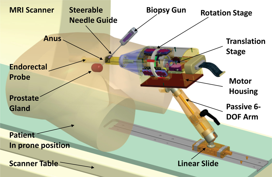
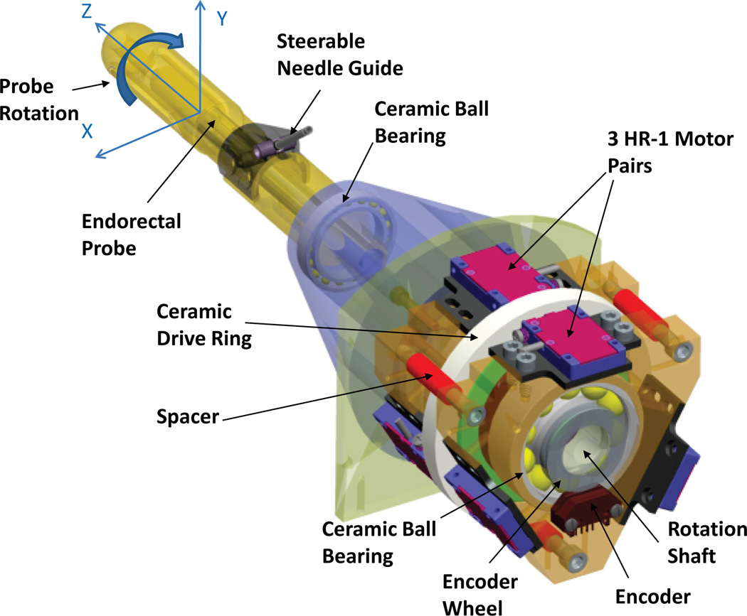
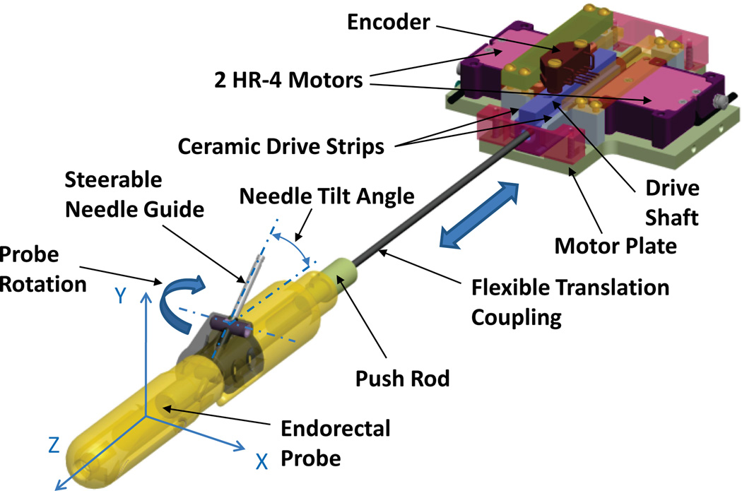
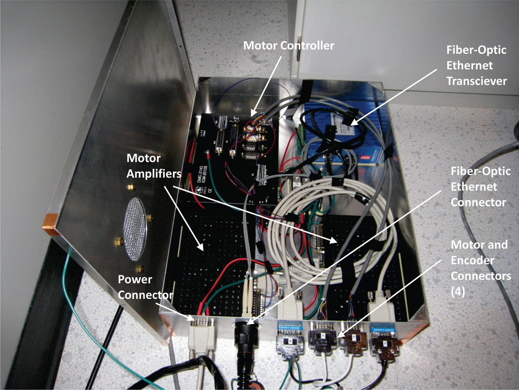
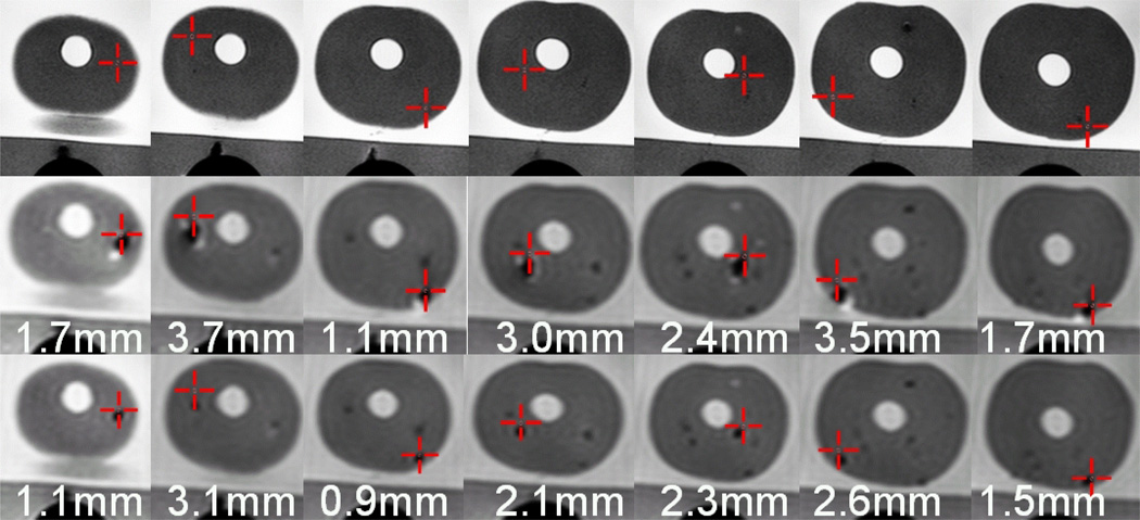
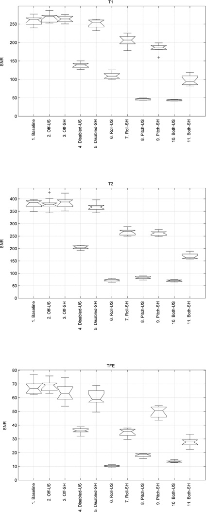
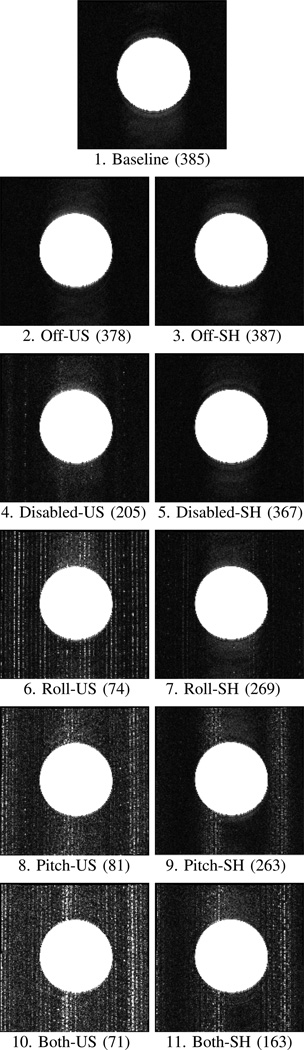
This paper reports the design, development, and magnetic resonance imaging (MRI) compatibility evaluation of an actuated transrectal prostate robot for MRI-guided needle intervention in the prostate. The robot performs actuated needle MRI-guidance with the goals of providing (i) MRI compatibility, (ii) MRI-guided needle placement with accuracy sufficient for targeting clinically significant prostate cancer foci, (iii) reducing interventional procedure times (thus increasing patient comfort and reducing opportunity for needle targeting error due to patient motion), (iv) enabling real-time MRI monitoring of interventional procedures, and (v) reducing the opportunities for error that arise in manually actuated needle placement. The design of the robot, employing piezo-ceramic-motor actuated needle guide positioning and manual needle insertion, is reported. Results of a MRI compatibility study show no reduction of MRI signal-to-noise-ratio (SNR) with the motors disabled. Enabling the motors reduces the SNR by 80% without RF shielding, but SNR is only reduced by 40% to 60% with RF shielding. The addition of radio-frequency shielding is shown to significantly reduce image SNR degradation caused by the presence of the robotic device. An accuracy study of MRI-guided biopsy needle placements in a prostate phantom is reported. The study shows an average in-plane targeting error of 2.4 mm with a maximum error of 3.7 mm. These data indicate the system's needle targeting accuracy is similar to that obtained with a previously reported manually actuated system, and is sufficient to reliably sample clinically significant prostate cancer foci under MRI-guidance.
Figures

Similar articles
-
Piezoelectrically Actuated Robotic System for MRI-Guided Prostate Percutaneous Therapy.IEEE ASME Trans Mechatron. 2015 Aug;20(4):1920-1932. doi: 10.1109/TMECH.2014.2359413. IEEE ASME Trans Mechatron. 2015. PMID: 26412962 Free PMC article.
-
Robotic system for MRI-guided prostate biopsy: feasibility of teleoperated needle insertion and ex vivo phantom study.Int J Comput Assist Radiol Surg. 2012 Mar;7(2):181-90. doi: 10.1007/s11548-011-0598-9. Epub 2011 Jun 23. Int J Comput Assist Radiol Surg. 2012. PMID: 21698389 Free PMC article.
-
System Integration and Preliminary Clinical Evaluation of a Robotic System for MRI-Guided Transperineal Prostate Biopsy.J Med Robot Res. 2019 Jun;4(2):1950001. doi: 10.1142/S2424905X19500016. Epub 2018 May 15. J Med Robot Res. 2019. PMID: 31485544 Free PMC article.
-
Image-guided prostate biopsy robots: A review.Math Biosci Eng. 2023 Jul 17;20(8):15135-15166. doi: 10.3934/mbe.2023678. Math Biosci Eng. 2023. PMID: 37679175 Review.
-
Review of Robotic Needle Guide Systems for Percutaneous Intervention.Ann Biomed Eng. 2019 Dec;47(12):2489-2513. doi: 10.1007/s10439-019-02319-9. Epub 2019 Jul 31. Ann Biomed Eng. 2019. PMID: 31372856 Review.
Cited by
-
State of the Art and Future Opportunities in MRI-Guided Robot-Assisted Surgery and Interventions.Proc IEEE Inst Electr Electron Eng. 2022 Jul;110(7):968-992. doi: 10.1109/jproc.2022.3169146. Epub 2022 May 3. Proc IEEE Inst Electr Electron Eng. 2022. PMID: 35756185 Free PMC article.
-
A Fully Actuated Body-Mounted Robotic Assistant for MRI-Guided Low Back Pain Injection.IEEE Int Conf Robot Autom. 2020 May-Aug;2020:10.1109/icra40945.2020.9197534. doi: 10.1109/icra40945.2020.9197534. Epub 2020 Sep 15. IEEE Int Conf Robot Autom. 2020. PMID: 34422445 Free PMC article.
-
Low temperature plasma: a novel focal therapy for localized prostate cancer?Biomed Res Int. 2014;2014:878319. doi: 10.1155/2014/878319. Epub 2014 Mar 13. Biomed Res Int. 2014. PMID: 24738076 Free PMC article. Review.
-
MRI-guided lumbar spinal injections with body-mounted robotic system: cadaver studies.Minim Invasive Ther Allied Technol. 2022 Feb;31(2):297-305. doi: 10.1080/13645706.2020.1799017. Epub 2020 Jul 30. Minim Invasive Ther Allied Technol. 2022. PMID: 32729771 Free PMC article.
-
Development and preliminary evaluation of a motorized needle guide template for MRI-guided targeted prostate biopsy.IEEE Trans Biomed Eng. 2013 Nov;60(11):3019-27. doi: 10.1109/TBME.2013.2240301. Epub 2013 Jan 15. IEEE Trans Biomed Eng. 2013. PMID: 23335658 Free PMC article.
References
-
- Krieger A, Iordachita I, Song S-E, Cho NB, Guion P, Fichtinger G, Whitcomb LL. Development and preliminary evaluation of an actuated MRI-compatible robotic device for MRI-guided prostate intervention. Proc. IEEE Int Robotics and Automation (ICRA) Conf; 2010. pp. 1066–1073.
-
- American Cancer Society. Cancer Facts and Figures 2010. Atlanta: American Cancer Society; 2010.
-
- Haker S, Mulkern R, Roebuck J, Barnes A, DiMaio S, Hata N, Tempany C. Magnetic resonance-guided prostate interventions. Topics in Magnetic Resonance Imaging. 2005;vol. 16(no. 5):355. - PubMed
-
- Presti JC. Prostate cancer: assessment of risk using digital rectal examination, tumor grade, prostate-specific antigen, and systematic biopsy. Radiologic Clinics of North America. 2000 Jan;vol. 38(no. 1):49–58. - PubMed
Grants and funding
LinkOut - more resources
Full Text Sources
Other Literature Sources