

Non-invasive characterization of polyurethane-based tissue constructs in a rat abdominal repair model using high frequency ultrasound elasticity imaging
- PMID: 23347836
- PMCID: PMC3565386
- DOI: 10.1016/j.biomaterials.2013.01.036
Non-invasive characterization of polyurethane-based tissue constructs in a rat abdominal repair model using high frequency ultrasound elasticity imaging
Abstract
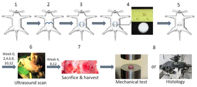
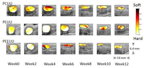
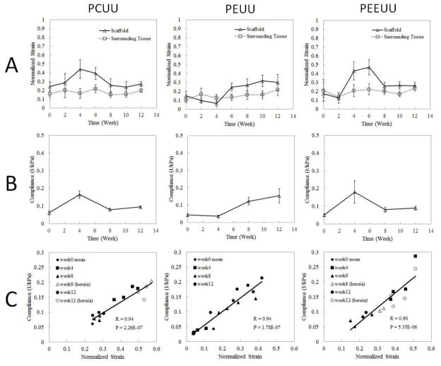
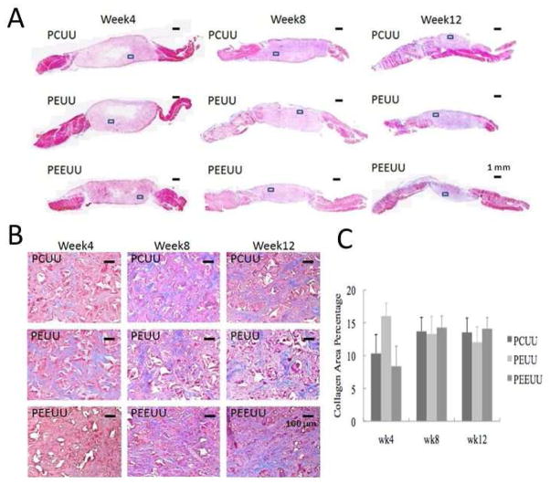
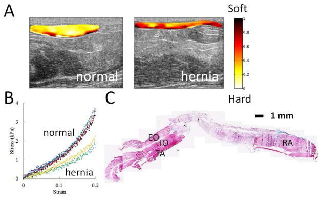
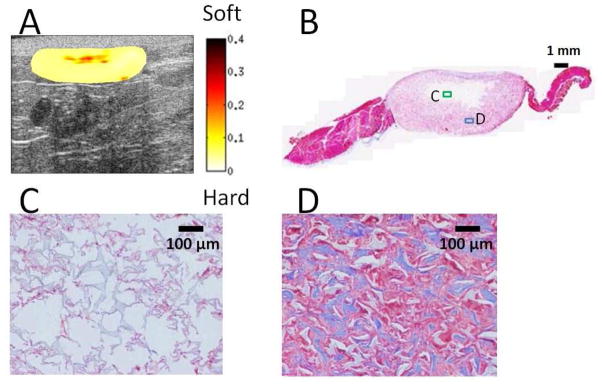
The evaluation of candidate materials and designs for soft tissue scaffolds would benefit from the ability to monitor the mechanical remodeling of the implant site without the need for periodic animal sacrifice and explant analysis. Toward this end, the ability of non-invasive ultrasound elasticity imaging (UEI) to assess temporal mechanical property changes in three different types of porous, biodegradable polyurethane scaffolds was evaluated in a rat abdominal wall repair model. The polymers utilized were salt-leached scaffolds of poly(carbonate urethane) urea, poly(ester urethane) urea and poly(ether ester urethane) urea at 85% porosity. A total of 60 scaffolds (20 each type) were implanted in a full thickness muscle wall replacement in the abdomens of 30 rats. The constructs were ultrasonically scanned every 2 weeks and harvested at weeks 4, 8 and 12 for compression testing or histological analysis. UEI demonstrated different temporal stiffness trends among the different scaffold types, while the stiffness of the surrounding native tissue remained unchanged. The changes in average normalized strains developed in the constructs from UEI compared well with the changes of mean compliance from compression tests and histology. The average normalized strains and the compliance for the same sample exhibited a strong linear relationship. The ability of UEI to identify herniation and to characterize the distribution of local tissue in-growth with high resolution was also investigated. In summary, the reported data indicate that UEI may allow tissue engineers to sequentially evaluate the progress of tissue construct mechanical behavior in vivo and in some cases may reduce the need for interim time point animal sacrifice.
Copyright © 2013 Elsevier Ltd. All rights reserved.
Figures
Similar articles
-
In vivo monitoring of structural and mechanical changes of tissue scaffolds by multi-modality imaging.Biomaterials. 2014 Sep;35(27):7851-9. doi: 10.1016/j.biomaterials.2014.05.088. Epub 2014 Jun 18. Biomaterials. 2014. PMID: 24951048 Free PMC article.
-
Tailoring the degradation kinetics of poly(ester carbonate urethane)urea thermoplastic elastomers for tissue engineering scaffolds.Biomaterials. 2010 May;31(15):4249-58. doi: 10.1016/j.biomaterials.2010.02.005. Epub 2010 Feb 25. Biomaterials. 2010. PMID: 20188411 Free PMC article.
-
Preparation and characterization of highly porous, biodegradable polyurethane scaffolds for soft tissue applications.Biomaterials. 2005 Jun;26(18):3961-71. doi: 10.1016/j.biomaterials.2004.10.018. Biomaterials. 2005. PMID: 15626443 Free PMC article.
-
Collagen: The superior material for full-thickness oral mucosa tissue engineering.J Oral Biosci. 2024 Sep;66(3):511-518. doi: 10.1016/j.job.2024.06.006. Epub 2024 Jun 21. J Oral Biosci. 2024. PMID: 38909983 Review.
-
Elastomeric Polyesters in Cardiovascular Tissue Engineering and Organs-on-a-Chip.Biomacromolecules. 2023 Nov 13;24(11):4511-4531. doi: 10.1021/acs.biomac.3c00387. Epub 2023 Aug 28. Biomacromolecules. 2023. PMID: 37639715 Free PMC article. Review.
Cited by
-
Imaging challenges in biomaterials and tissue engineering.Biomaterials. 2013 Sep;34(28):6615-30. doi: 10.1016/j.biomaterials.2013.05.033. Epub 2013 Jun 13. Biomaterials. 2013. PMID: 23768903 Free PMC article.
-
Noninvasive Quantitative Imaging of Collagen Microstructure in Three-Dimensional Hydrogels Using High-Frequency Ultrasound.Tissue Eng Part C Methods. 2015 Jul;21(7):671-82. doi: 10.1089/ten.TEC.2014.0527. Epub 2015 Mar 12. Tissue Eng Part C Methods. 2015. PMID: 25517512 Free PMC article.
-
Naturally derived and synthetic scaffolds for skeletal muscle reconstruction.Adv Drug Deliv Rev. 2015 Apr;84:208-21. doi: 10.1016/j.addr.2014.08.011. Epub 2014 Aug 29. Adv Drug Deliv Rev. 2015. PMID: 25174309 Free PMC article. Review.
-
Medical imaging of tissue engineering and regenerative medicine constructs.Biomater Sci. 2021 Jan 21;9(2):301-314. doi: 10.1039/d0bm00705f. Epub 2020 Aug 10. Biomater Sci. 2021. PMID: 32776044 Free PMC article. Review.
-
Radiopaque scaffolds based on electrospun iodixanol/polycaprolactone fibrous composites.Materialia (Oxf). 2020 Dec;14:100874. doi: 10.1016/j.mtla.2020.100874. Epub 2020 Aug 22. Materialia (Oxf). 2020. PMID: 32954230 Free PMC article.
References
-
- Martinez-Diaz S, Garcia-Giralt N, Lebourg M, Gomez-Tejedor JA, Vila G, Caceres E, et al. In vivo evaluation of 3-dimensional polycaprolactone scaffolds for cartilage repair in rabbits. Am J Sports Med. 2010;38:509–19. - PubMed
-
- Yoshikawa M, Yabuuchi T, Tsuji N, Shimomura Y, Hayashi H, Ohgushi H. In vivo osteogenesis in porous hydroxyapatite scaffold processed in hyaluronic acid solution. Key Eng Mater. 2008;361–363:1185–8.
-
- VandeVord PJ, Matthew HWT, DeSilva SP, Mayton L, Wu B, Wooley PH. Evaluation of the biocompatibility of a chitosan scaffold in mice. J Biomed Mater Res. 2002;59:585–90. - PubMed
-
- Lee WK, Ichi T, Ooya T, Yamamoto T, Katoh M, Yui N. Novel poly(ethylene glycol) scaffolds crosslinked by hydrolyzable polyrotaxane for cartilage tissue engineering. J Biomed Mater Res. 2002;67A:1087–92. - PubMed
Publication types
MeSH terms
Substances
Grants and funding
LinkOut - more resources
Full Text Sources
Other Literature Sources
