. 2013 Jul;26(3):378-96.
doi: 10.1007/s10548-012-0274-6. Epub 2013 Jan 26.

Effects of forward model errors on EEG source localization

Affiliations

Effects of forward model errors on EEG source localization

Zeynep Akalin Acar et al. Brain Topogr. 2013 Jul.

Abstract

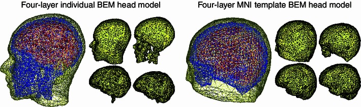
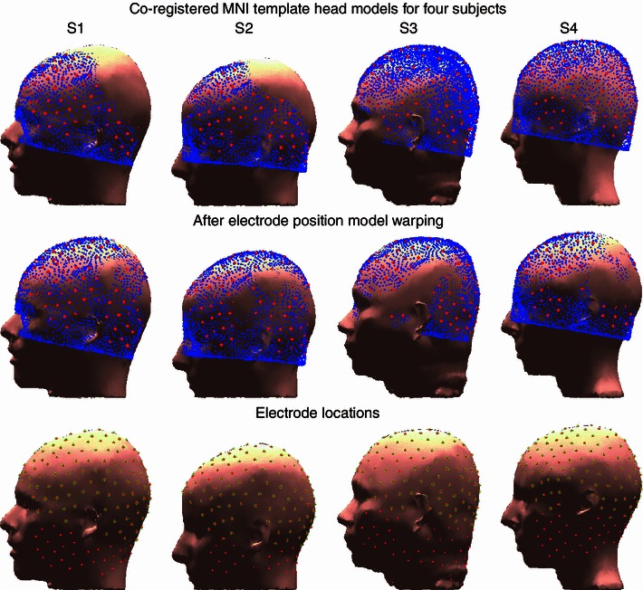
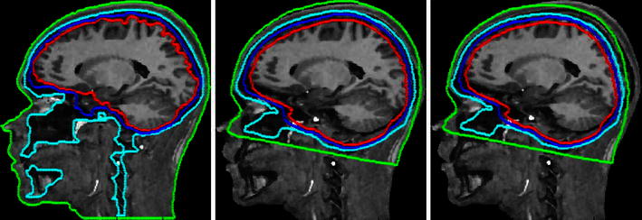
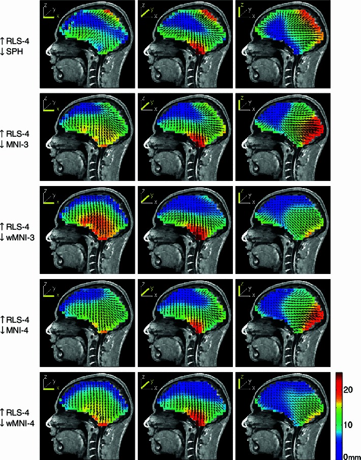
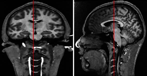
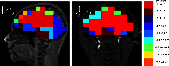
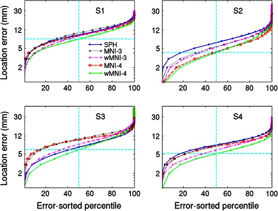
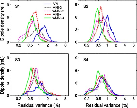
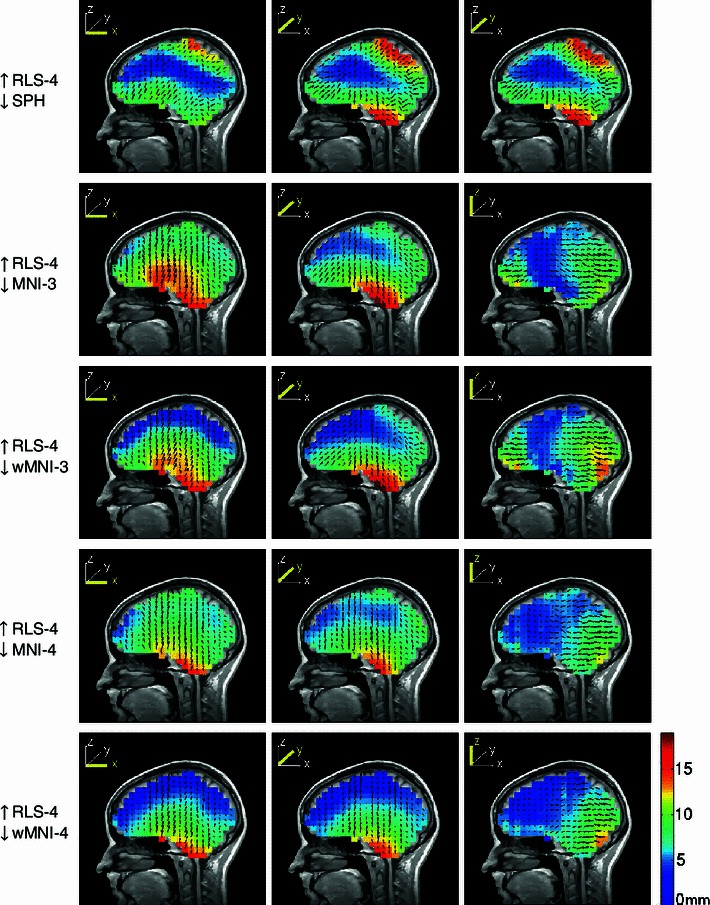
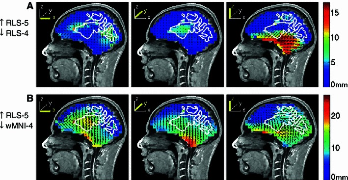
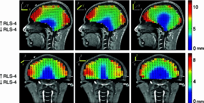
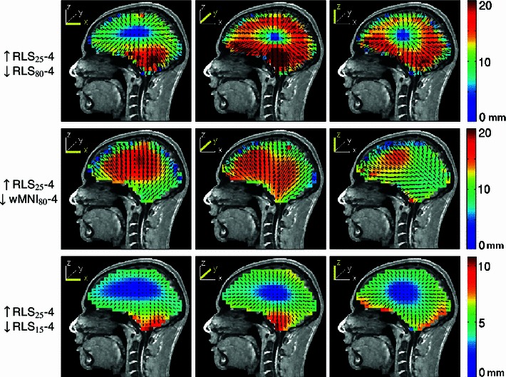
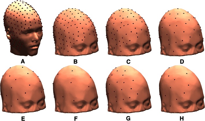
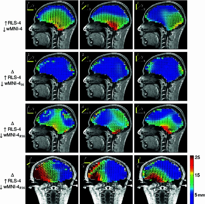
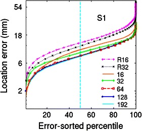
Subject-specific four-layer boundary element method (BEM) electrical forward head models for four participants, generated from magnetic resonance (MR) head images using NFT ( www.sccn.ucsd.edu/wiki/NFT ), were used to simulate electroencephalographic (EEG) scalp potentials at 256 recorded electrode positions produced by single current dipoles of a 3-D grid in brain space. Locations of these dipoles were then estimated using gradient descent within five template head models fit to the electrode positions. These were: a spherical model, three-layer and four-layer BEM head models based on the Montreal Neurological Institute (MNI) template head image, and these BEM models warped to the recorded electrode positions. Smallest localization errors (4.1-6.2 mm, medians) were obtained using the electrode-position warped four-layer BEM models, with largest localization errors (~20 mm) for most basal brain locations. When we increased the brain-to-skull conductivity ratio assumed in the template model scalp projections from the simulated value (25:1) to a higher value (80:1) used in earlier studies, the estimated dipole locations moved outwards (12.4 mm, median). We also investigated the effects of errors in co-registering the electrode positions, of reducing electrode counts, and of adding a fifth, isotropic white matter layer to one individual head model. Results show that when individual subject MR head images are not available to construct subject-specific head models, accurate EEG source localization should employ a four- or five-layer BEM template head model incorporating an accurate skull conductivity estimate and warped to 64 or more accurately 3-D measured and co-registered electrode positions.


Figures

Fig. 1
Fig. 1
A realistic head model generated from a subject T1-weighted whole head MR image (left) and an MNI template model fit to the same (subject S1) head (right). The four shells of the BEM models (scalp, skull, CSF, and grey matter) are shown to the right of each model
Fig. 2
Fig. 2
Registered (upper row) and head shape-warped (middle row) MNI template model scalp meshes plotted on the scalp surface of the reference head models with co-registered MNI electrode locations. Co-registered electrode locations with the subjects’ scalp surfaces (red dots) and selected electrodes used in MNI and spherical head model source localization (green circles) are shown in the lower row
Fig. 3
Fig. 3
Scalp, skull, CSF and brain tissue boundaries for a four-layer MR-based realistic, b four-layer warped MNI, and c four-layer MNI head models plotted on a sagittal slice of subject S1
Fig. 4
Fig. 4
Equivalent dipole source localization error directions (arrows) and magnitudes (colors) for spherical (top row) and four MNI-template based head models computed from source dipole scalp projections computed using a four-layer realistic subject MR image based BEM forward head model (subject S1 in Fig. 2). The forward and inverse models are indicated to the left of each row (up arrow forward model, down arrow inverse model). The source space was a regular Cartesian grid of single current dipole sources with 8-mm spacing filling the brain volume. The three columns show the errors for equivalent dipole sources that were oriented in x, y, and z directions, respectively (see insets). Note that, maximum error shown was 25 mm so as to use the same scaling for all the plots while retaining some contrast for the lower-error plots. Maximum localization errors were given in Table 3
Fig. 5
Fig. 5
Selected coronal and sagittal slices to show localization errors
Fig. 6
Fig. 6
Sagittal and coronal slice dipole-error maps showing, for each slice-transversed voxel, the dipole direction with the largest localization error
Fig. 7
Fig. 7
Magnitude-sorted localization error distributions in four subjects (S1–S4) for source localization performed using spherical (blue) or MNI template-based head models, each showing best localization performance for the 4-layer electrode position-warped MNI template head model (WMNI-4)
Fig. 8
Fig. 8
Histograms of percent residual scalp map variance for source estimates based on spherical or MNI-based head models for the four subjects (S1–S4), each showing best fits for the 4-layer electrode position-warped MNI template head model (WMNI-4) and poorest fits for the spherical head model (SPH)
Fig. 9
Fig. 9
Mean dipole source localization error directions (arrows) and magnitudes (colors) for four subjects using spherical and MNI template-based head models to localize equivalent dipole sources simulated in a subject-specific four-layer realistic BEM head model. Other details as in Fig. 3
Fig. 10
Fig. 10
High-resolution white matter segmentation obtained using FreeSurfer (left), and the decimated BEM white matter mesh (right) consisting of 10,240 triangular faces
Fig. 11
Fig. 11
Equivalent dipole source localization error directions (arrows) and magnitudes (colors) relative to simulated dipole projections using a four-layer reference head model (S1) for EEG data simulated using a five-layer BEM head model including a white matter layer. The white matter boundary in the five-layer model is outlined in white. Other details as in Fig. 3
Fig. 12
Fig. 12
Equivalent dipole source localization error directions (arrows) and magnitudes (colors) in a four-layer reference BEM head model when the co-registered scalp electrode positions were tilted 5° backwards (top row), or 5° to the left (bottom row) before dipole localization. White arrows in the left most panels show the approximate size of the simulated co-registration error. Other details as in Fig. 3
Fig. 13
Fig. 13
Equivalent dipole source localization error directions (arrows) and magnitudes (colors) for model dipoles in a four-layer realistic BEM head model when the brain-to-skull conductivity ratio was mis-estimated as 80:1 (top row) or as 15:1 (bottom row) instead of the simulated forward-model value (25:1). The middle row shows errors when source localization was performed using a warped four-layer MNI head model and the forward model brain-to-skull ratio was again mis-estimated as 80:1. Note that, maximum error shown was 20 mm for top and bottom rows so as to use the same scaling while retaining some contrast for the lower-error plots. Maximum localization errors were given in Table 3. Other details as in Fig. 3
Fig. 14
Fig. 14
a 256 sensor locations on the S1 reference head model. bf 192, 128, 64, 32, and 16 distributed sensor locations on the S1 head shape-warped (wMNI-4) template model. gh 32 and 16 sensor locations placed only on the right side of the template model
Fig. 15
Fig. 15
Top-row equivalent dipole source localization error directions (arrows) and magnitudes (colors) for a head shape-warped four-layer MNI head model using 192 electrodes (from Fig. 3). The lowerthreerows show additional errors introduced by using only 16 uniformly distributed electrodes (subscript 16, second row), or using 16 electrodes covering only right side of the head (subscript R16, bottom rows)
Fig. 16
Fig. 16
Magnitude-sorted localization error distributions (subject S1) for source localizations performed using the sensor distributions shown in Fig. 14ch and the wMNI-4 template head model
Fig. 17
Fig. 17
Cortical regions of subject S1 brain. Segmentation obtained using FreeSurfer

References

    1. Akalin Acar Z, Gencer NG. An advanced BEM implementation for the forward problem of electro-magnetic source imaging. Phys Med Biol. 2004;49(5):5011–5028. doi: 10.1088/0031-9155/49/21/012. - DOI - PubMed
    1. Akalin Acar Z, Makeig S. Neuroelectromagnetic forward head modeling toolbox. J Neurosci Methods. 2010;190:258–270. doi: 10.1016/j.jneumeth.2010.04.031. - DOI - PMC - PubMed
    1. Akalin Acar Z, Makeig S (2012) EEG cortical patch sources and equivalent dipole source localization. In: HBM 2012, New Orleans
    1. Akalin Acar Z, Worrell G, Makeig S. Patch based electrocortical source imaging in epilepsy. IEEE Eng Med Biol Soc. 2009;2009:2930–2933. - PMC - PubMed
    1. Ataseven Y, Akalin Acar Z, Acar CE, Gencer NG. Parallel implementation of the accelerated BEM approach for EMSI of the human brain. Med Biol Eng Comput. 2008;46:671–679. doi: 10.1007/s11517-008-0316-0. - DOI - PubMed

Publication types