. 2013 Feb 26;110(9):3276-81.
doi: 10.1073/pnas.1217998110. Epub 2013 Feb 11.

Geometry of Miura-folded metamaterials

Affiliations

Geometry of Miura-folded metamaterials

Mark Schenk et al. Proc Natl Acad Sci U S A. .

Abstract

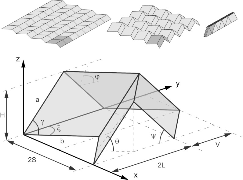
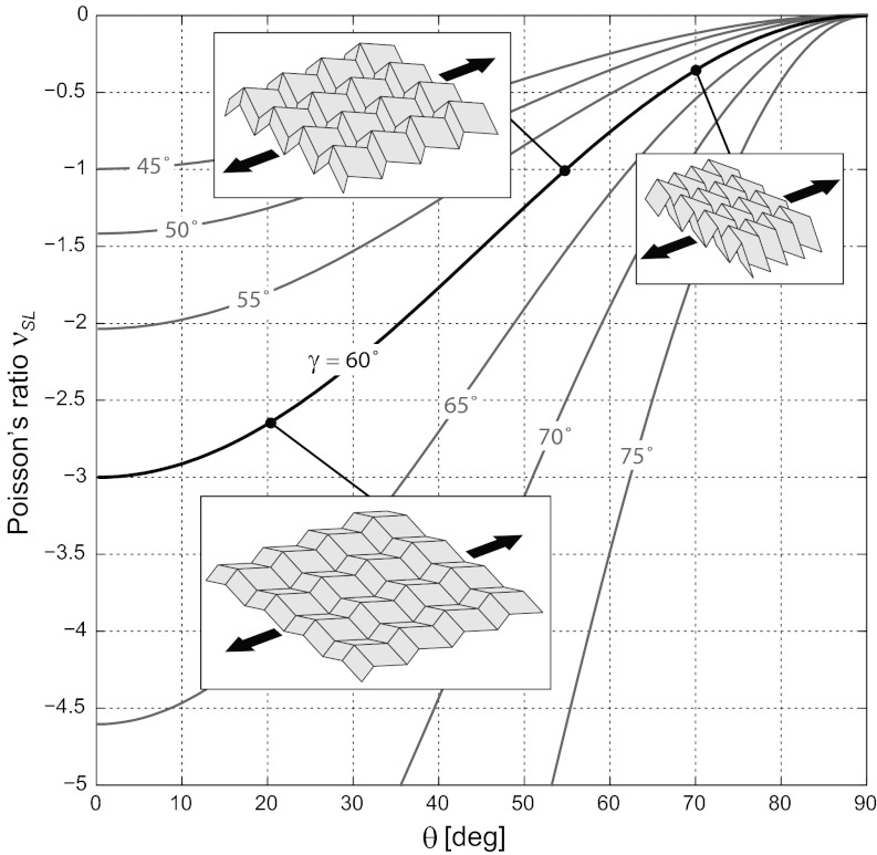
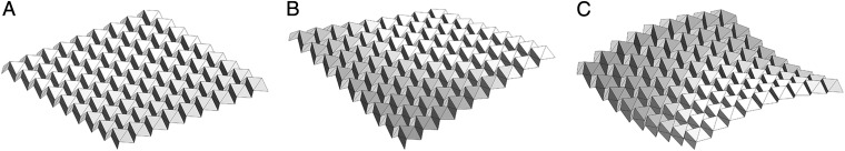
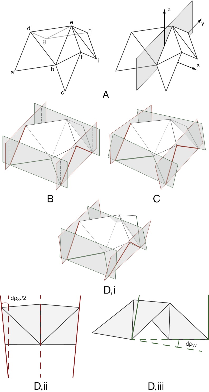
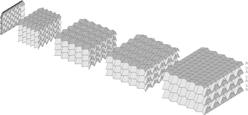
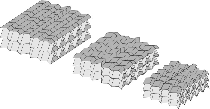
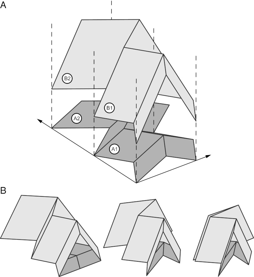
This paper describes two folded metamaterials based on the Miura-ori fold pattern. The structural mechanics of these metamaterials are dominated by the kinematics of the folding, which only depends on the geometry and therefore is scale-independent. First, a folded shell structure is introduced, where the fold pattern provides a negative Poisson's ratio for in-plane deformations and a positive Poisson's ratio for out-of-plane bending. Second, a cellular metamaterial is described based on a stacking of individual folded layers, where the folding kinematics are compatible between layers. Additional freedom in the design of the metamaterial can be achieved by varying the fold pattern within each layer.


Conflict of interest statement

The authors declare no conflict of interest.

Figures

Fig. 1.
Fig. 1.
A folded Miura-ori sheet consists of tessellations of a unit cell. The unit cell geometry can be described using parameters defining a parallelogram facet, a, b, γ, and fold angle θ ∈ [0, π/2]. An alternative parameterization is given by dimensions H, S, V, L. Other useful angles are shown, where ξ and ψ are angles between fold lines and the y axis and θ and φ are dihedral angles between facets and the xy and yz planes, respectively. Three configurations with θ = {0, π/4, π/2} are shown.
Fig. 2.
Fig. 2.
The in-plane expansion coefficient of a Miura-ori sheet, νSL = −cos2θ tan2γ, for different geometries γ. The arrows indicate the primary strain direction δS; pictured are configurations with γ = 60° and a/b = 1.
Fig. 3.
Fig. 3.
(A) The undeformed configuration and the (B) twisting and (C) saddle-shaped deformation modes of a Miura sheet with 9 × 9-unit cells (a/b = 1, γ = π/3). It is shown in ref. that, over a wide range of geometries and material parameters, these deformation modes are the most flexible. Only for configurations where the bending stiffness of the facets is much greater than the bending stiffness of the fold lines is the planar mechanism (Fig. 1) the most flexible deformation mode.
Fig. 4.
Fig. 4.
To capture out-of-plane deformations, (A) additional fold lines (bd, bf, eg, and ei) are introduced diagonally across the facets. (B) The deformations of the unit cells can be visualized by means of bounding planes, which represent the tessellation boundary conditions ∠adg = ∠cfi and ∠abc = ∠ghi. The resulting out-of-plane deformation modes are (C) twisting and (D) saddle-shaped bending, which are, respectively, antisymmetric and symmetric in the yz plane (15). (D, i) For the bending mode, the tilt angles of the bounding planes, xx and yy, can be converted to a corresponding change in curvature of the folded sheets: (D, ii) κxx = xx/2S; (D, iii) κyy = yy/2L. Additional details are in SI Appendix.
Fig. 5.
Fig. 5.
Individual Miura-ori sheets can be stacked together and bonded along joining fold lines to form a folded cellular metamaterial. Although the Miura-ori unit cell geometry varies between successive layers, the stacked configuration preserves the folding kinematics, and the 3D metamaterial expands/contracts uniformly. Here, a stack with alternating layers ABABABA is shown. An animation of the folding motion is provided by Movie S1.
Fig. 6.
Fig. 6.
A self-locking folded cellular metamaterial. As the Miura sheets contract, the unit cells in the central column reach their maximum fold angle before the rest of the layer, thereby halting the folding motion and locking the metamaterial in a predetermined configuration. This behavior can be achieved by varying the unit cell geometry within each layer. An animation of the folding motion is provided by Movie S2.
Fig. 7.
Fig. 7.
The unit cell geometry of the Miura pattern can be varied within each layer. A shows layer A with unit cells A1 and A2, on which are stacked unit cells B1 and B2 in layer B. The relationship between the unit cell geometries is given by Eq. 21. The geometry γA2 < γA1 is selected such that unit cells A2 and B2 will lock in a predetermined configuration, which is shown in B.

References

    1. Miura K. Method of packaging and deployment of large membranes in space. Inst Space Astronaut Sci Rep. 1985;618:1–9.
    1. Tanizawa K, Miura K. Large displacement configurations of bi-axially compressed infinite plate. Trans Jpn Soc Aeronaut Space Sci. 1978;20(50):177–187.
    1. Mahadevan L, Rica S. Self-organized origami. Science. 2005;307(5716):1740. - PubMed
    1. Klett Y, Drechsler K. Designing technical tessellations. In: Wang-Iverson P, Lang RJ, Yim M, editors. Origami 5: Fifth International Meeting of Origami Science, Mathematics, and Education (5OSME) Boca Raton, FL: CRC; 2011. pp. 305–322.
    1. Lebée A, Sab K. Transverse shear stiffness of a chevron folded core used in sandwich construction. Int J Solids Struct. 2010;47(18–19):2620–2629.