

doi: 10.1038/srep01258.
Epub 2013 Feb 13.
Integrated microfluidic device for single-cell trapping and spectroscopy
Affiliations
- PMID: 23409249
- PMCID: PMC3570777
- DOI: 10.1038/srep01258
Item in Clipboard
Integrated microfluidic device for single-cell trapping and spectroscopy
Sci Rep.
2013.
Erratum in
- Sci Rep. 2013 Mar 1;3. doi: 10.1371/annotation/a26cb527-ec18-46ec-a63f-c69d0983add6 doi: 10.1371/annotation/a26cb527-ec18-46ec-a63f-c69d0983add6
Abstract
Optofluidic microsystems are key components towards lab-on-a-chip devices for manipulation and analysis of biological specimens. In particular, the integration of optical tweezers (OT) in these devices allows stable sample trapping, while making available mechanical, chemical and spectroscopic analyses.
Figures
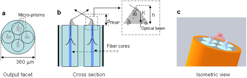
(a) front-view of the output facet, showing the four fibres with microprisms. (b) cross-section of the fibre probe, the beams propagating in two symmetrically positioned fibres are reflected at the interface between microprisms and the outer medium; as reported in the inset, the prism angles are chosen so as to produce normal incidence on the second interface. (c) isometric representation of the optical tweezers trapping a particle.
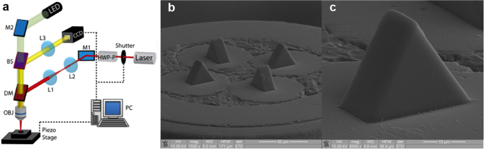
(a) Diagram of the experimental TPL setup: HWP-P – variable attenuator; L1 and L2 lenses for beam expander; L3 imaging tube lens; BS – beam splitter, DM – dichroic mirror and OBJ – microscope objective; M1 and M2 – mirrors. Details on the fabrication technique are reported in the methods section. (b) SEM image of the end-face of the fibre-tweezers. The prisms completely cover the fibres' core. (c) Detail of a single prism: the roughness of the surface is below 100 nm, thus not affecting the optical quality of the transmitted beam.
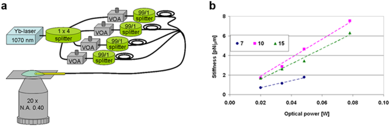
(a) all-fibre optical set-up exploited to test the trapping efficiency of the fibre tweezers. VOA: Variable optical attenuator, for sake of simplicity the 1% output of the 99/1 splitter is not shown in the scheme. (b) trapping stiffness, as a function of the optical power, considering polystyrene beads. The power-normalized stiffness is given by the slope of the linear fit, for each particle size. According to the collected data, the stiffness lower limit is about 94, 78 and 35 pN μm-1 W-1 for beads with a diameter of 10, 15 and 7 μm, respectively.
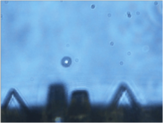
Frame taken from the video reported in Supplementary Video S1, showing the probe tip (with four protruding prisms) used to trap and move a red blood cell in hypotonic solution.
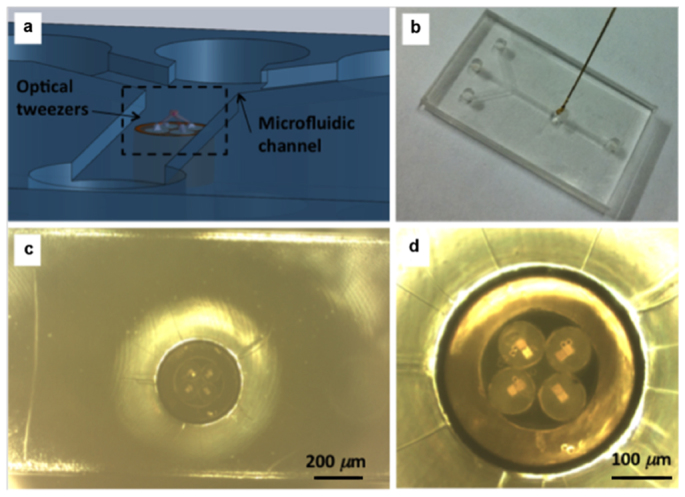
(a) Isometric view of the optical tweezers integrated in the microfluidic system (the schematic diagram shows an overturned view of the top layer for in order to have a better visualization). (b) Top view picture of the device. (c) Zoomed picture of the optical tweezers inside the microfluidic channel (whose lateral walls are also visible at top and bottom of the picture). (d) Zoomed picture of the microprisms on the optical tweezers.
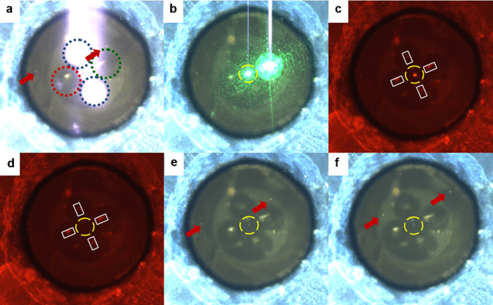
Sequence of images obtained starting from the frames of Supplementary Video S2. (a) Front-view of the probe: the two fibres indicated by the blue dotted line emit the infrared radiation used to trap the particle. The fibre surrounded by the green circle is connected to the 532-nm laser source, while the one surrounded by the red circle is unused. Red arrows indicate the position of two non-trapped beads. (b) After inserting an IR-filter and switching on the 532-nm laser the green light scattered by the trapped particle (inside the yellow, dashed circle) is evident. (c) A long-pass filter is introduced in the light path to remove the 532-nm radiation from the image and the trapped bead (7.5 μm in diameter) shows an evident red fluorescence. (d) When the 532-nm laser is switched off the fluorescence disappear: the red light visible in the picture is given by coaxial white-light illumination used to illuminate the scene. (e) When the long-pass filter is removed, and the IR-filter is used, it is possible to observe the trapped bead in the centre of the yellow circle, as well as two additional beads indicated by the red arrows. (f) When the flow is restored the trapped bead remains stably trapped, while the other beads flow towards the upper right corner.
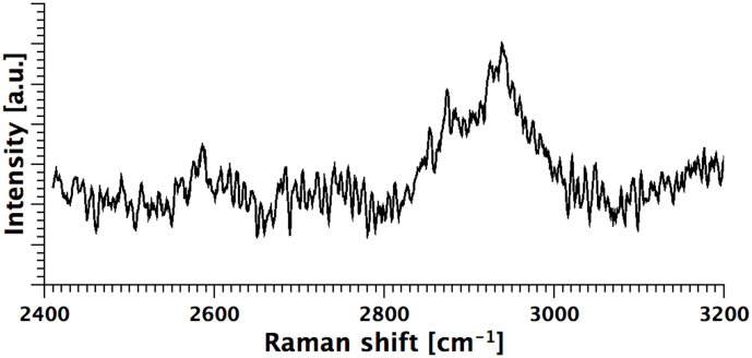
Raman signature of a colon cancer cell in the C-H stretch Raman band, which is typically dominated by the lipidic and protein content. The Raman scattering has been collected through a microscope objective and measured by a commercial spectrometer.
References
-
- El-Ali J., Sorger P. K. & Jensen K. F. Cells on chips. Nature 442, 403–11 (2006). - PubMed
-
- Psaltis D., Quake S. R. & Yang C. Developing optofluidic technology through the fusion of microfluidics and optics. Nature 442, 381–6 (2006). - PubMed
-
- Chiou A. et al. Optical Trapping and Manipulation for Biomedical Applications. In L. Pavesi & P. M. Fauchet (Eds). Biophotonics, 249–273 (Springer Berlin Heidelberg, 2008).
-
- Cojoc D. et al. Properties of the Force Exerted by Filopodia and Lamellipodia and the Involvement of Cytoskeletal Components. PLoS ONE, doi:10.1371/journal.pone.0001072 (2007). - DOI - PMC - PubMed
Publication types
LinkOut - more resources
Full Text Sources
Other Literature Sources
Miscellaneous
