. 2013 May;109(9):2293-305.
doi: 10.1152/jn.00499.2012. Epub 2013 Feb 20.

Single-subject fMRI mapping at 7 T of the representation of fingertips in S1: a comparison of event-related and phase-encoding designs

Affiliations

Single-subject fMRI mapping at 7 T of the representation of fingertips in S1: a comparison of event-related and phase-encoding designs

Julien Besle et al. J Neurophysiol. 2013 May.

Abstract

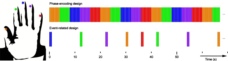
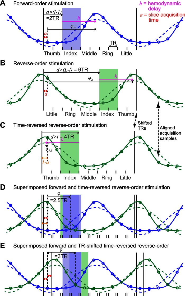
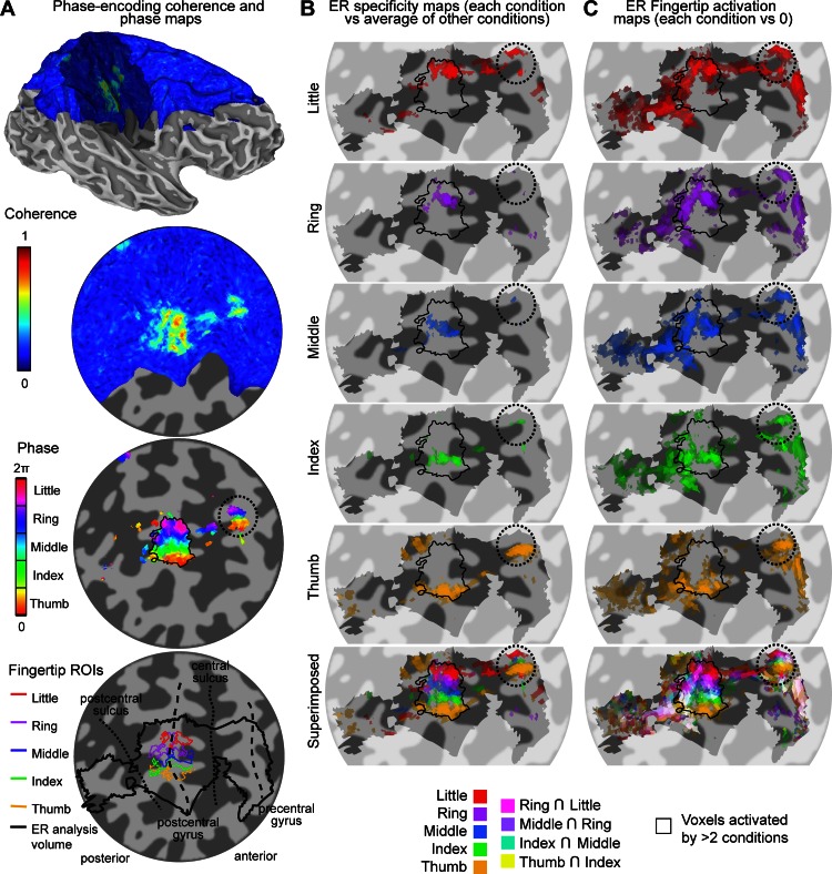
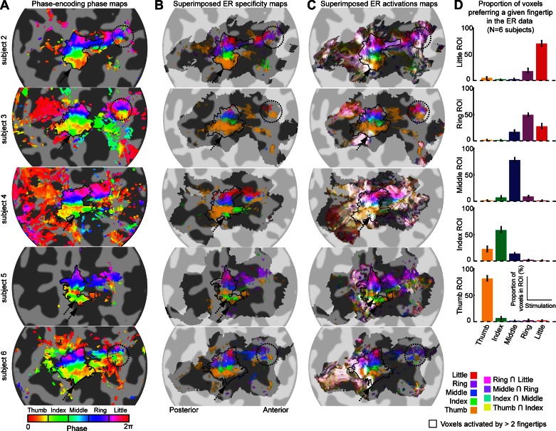
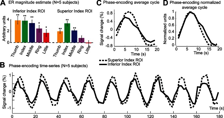
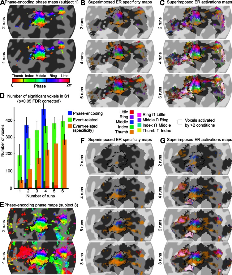
A desirable goal of functional MRI (fMRI), both clinically and for basic research, is to produce detailed maps of cortical function in individual subjects. Single-subject mapping of the somatotopic hand representation in the human primary somatosensory cortex (S1) has been performed using both phase-encoding and block/event-related designs. Here, we review the theoretical strengths and limits of each method and empirically compare high-resolution (1.5 mm isotropic) somatotopic maps obtained using fMRI at ultrahigh magnetic field (7 T) with phase-encoding and event-related designs in six subjects in response to vibrotactile stimulation of the five fingertips. Results show that the phase-encoding design is more efficient than the event-related design for mapping fingertip-specific responses and in particular allows us to describe a new additional somatotopic representation of fingertips on the precentral gyrus. However, with sufficient data, both designs yield very similar fingertip-specific maps in S1, which confirms that the assumption of local representational continuity underlying phase-encoding designs is largely valid at the level of the fingertips in S1. In addition, it is shown that the event-related design allows the mapping of overlapping cortical representations that are difficult to estimate using the phase-encoding design. The event-related data show a complex pattern of overlapping cortical representations for different fingertips within S1 and demonstrate that regions of S1 responding to several adjacent fingertips can incorrectly be identified as responding preferentially to one fingertip in the phase-encoding data.

Keywords: high-field MRI; high-resolution functional MRI; human; somatosensory cortex; tactile perception.


Figures

Fig. 1.
Fig. 1.
Timing of stimuli and experimental designs. Top: phase-encoding design in which the fingertips are stimulated sequentially either from thumb (D1) to little finger (D5) or in the reverse order (data not shown). Each color bar represents 0.4 s of continuous 50-Hz fingertip stimulation (yellow, D1; green, D2; blue, D3; magenta, D4; and red, D5). Note, for the phase-encoding design, there are no periods of rest between consecutive fingertip stimulations. Bottom: event-related (ER) design with intertrial interval of between 4- and 12-s duration. Each vibrotactile event was formed of 2 periods of vibrotactile 50-Hz stimulation lasting 0.4 s separated by 0.1 s.
Fig. 2.
Fig. 2.
Phase computation and independence from slice acquisition time and hemodynamic response function (HRF) delay for phase-encoding data (see appendix for details). A: solid blue line models the time series of activation of a hypothetical voxel responding only to the index finger (2nd location, l = 2), in a phase-encoding run in which fingertips are stimulated from the thumb to the little finger (total number of locations, L = 5). Only 1 cycle of the stimulation is illustrated. The fingertip that is being stimulated changes every 2nd repetition time (TR), at the start of the TR period, as described in the main text. Each circle on the curve represents a time point sampled at an unknown acquisition time, a, after the start of each TR period. The activation corresponding to the stimulation of an individual fingertip is modeled as a boxcar function with a period of 10 TR and an on period d = 2 TR, convolved with a double-γ HRF model. Dashed blue line: best-fitting cosine function. φF, phase of the cosine function (relative to the acquisition time of the 1st sample in the stimulation cycle, expressed in TR), as measured in the phase-encoding analysis described in the text. The best-fitting cosine peaks after an unknown delay, h, relative to the start of stimulation, due to the hemodynamic delay. B: as for A but for reverse-order stimulation. C: in the phase-encoding analysis, reverse-order stimulation runs are time-reversed relative to forward-order runs. However, this reversal is limited by the acquisition sampling (1 sample every TR). This is illustrated by the fact that acquisition samples, but not the actual start of TR/stimulation, are aligned between B and C as highlighted by the arrows. D: superimposed model activation for forward stimulation and time-reversed, reversed-order stimulations model. The 2 model activations (and corresponding best-fitting cosine) are mirror images of each other. In the phase-encoding analysis, the phase is computed as the complex average of the phase of both acquired time series (the amplitude is ignored) and therefore corresponds to the point of symmetry of the forward-order and time-reversed, reverse order time series. Because the phase is computed relative to acquisition sample times (circles), the point of symmetry is independent of both a and h (see appendix for details) and corresponds to exactly 2.5 TR. E: to make the phase values easier to interpret, we shift the time-reversed, reverse-order time series by an additional TR so that the point of symmetry is moved forward by half of a TR. Now the phase for a voxel activated uniquely by the index fingertip is predicted to be exactly 3TR/10TR×2π = 3π/10, which is the center of the [π/5 2π/5] phase bin.
Fig. 3.
Fig. 3.
Procedures to obtain somatotopic maps from the phase-encoding and ER data in subject 1. A: phase-encoding design. Coherence maps, phase maps, and regions of interest (ROIs) are displayed on inflated 3-dimensional (3-D) model of the right hemisphere cortical surface (top) and flattened cortical patch (bottom 3 maps). Dark gray, areas of negative curvature (sulci); light gray, areas of positive curvature (gyri); shaded area on the 3-D model, location of the cortical flat patch. Coherence values are given by finding the maximum intensity projection of coherence across coordinates corresponding to different cortical depths. Note that not all surface points of the patch have an associated value because of the partial field of view (FOV) of the functional images as shown in blue. Phase maps for the corresponding data set are thresholded at a coherence value equivalent to a false discovery rate (FDR)-adjusted P value of 0.05. Phase values (in radians) represent corresponding preferred stimulus location (fingertip). Phase values are complex-averaged across cortical depths using phase and amplitude values at each depth. Colored outline in bottom map, fingertip-specific ROIs defined as all contiguous voxels within the cortical sheet with significant coherence values (P < 0.05, FDR-adjusted). Thick black outline, volume in which the ER analysis was performed to limit number of multiple comparisons (constructed by expanding the 5 fingertip ROIs by 5 voxels in 3-D space). Thin black outline in phase map, union of 5 finger-specific ROIs. B: fingertip specificity maps (each stimulation condition compared with the average of 4 other stimulation conditions), displayed on a flattened cortical patch. The saturation of each color map represents the amplitude of the contrast estimate. Transparency represents the corresponding statistical significance (thresholded at P < 0.05, FDR-corrected). Shaded area, voxels included in the analysis. Bottom map: superimposed maps of all fingertip conditions using the color blending scheme described in materials and methods (Alignment and Projection of Statistical Maps onto Surfaces and Flattened Patches). C: same as B but for fingertip activation (each stimulation condition compared with 0).
Fig. 4.
Fig. 4.
Comparison of phase-encoding and ER data in subjects 2–6. Each row shows data from 1 subject. A: somatotopic (phase) maps from phase-encoding experiment (see Fig. 3A for details). B: superimposition of all fingertip specificity maps (see Fig. 3B for details) shows tight correspondence with fingertip-specific maps from phase-encoding experiment (A). C: superimposition of all fingertip activation maps (see Fig. 3C for details) shows important overlap of activation in the posterior part of the somatotopic representation in S1. D: proportion of voxels in each phase-encoding ROI that respond maximally in each of the 5 fingertip stimulation conditions of the ER design. In each ROI, the majority of voxels responded maximally to the finger expected from the phase-encoding design.
Fig. 5.
Fig. 5.
ER and phase-encoding responses in inferior and superior “index-specific” ROIs. A: ER parameter estimates for each of the 5 fingertip stimulation regressors (magnitude component) averaged across voxels in the inferior ROI and superior index-specific ROIs and across 5 subjects. Error bars, standard error across subjects. *P < 0.05, **P < 0.01, statistical significance compared with 0, corrected for multiple comparison using Hommel's modified Bonferroni procedure. B: phase-encoding time series for the inferior and superior index-specific ROIs averaged across 5 subjects, across voxels, and across forward-order and time-reversed, reverse-order runs. C: response to a single cycle of the phase-encoding design averaged across cycles. D: as for C after normalization of each subject's time series between 0 and 1 and shifting the data of the inferior index ROI by 2/3 of a TR (1.66 s) to align the rising edges of the response in each ROI.
Fig. 6.
Fig. 6.
Effect of the number of scans included in the analysis. A: phase maps formed from the phase-encoding data acquired in 2 or 4 runs, thresholded at a coherence value of 0.25. Phase values (in radians) represent corresponding preferred stimulus location (fingertip). Phase values are complex-averaged across cortical depths using phase and amplitude values at each depth. Runs of the phase-encoding design were of 3-min duration for this subject. The maps constructed using 2 or 4 scans are very similar, suggesting that 2 runs (6 min) are sufficient to yield robust maps. B: superimposed fingertip specificity maps (see Fig. 3B for details) for 2, 4, and 6 runs. Runs of the ER design were 4 min long. Each addition of 2 runs improves the maps found up to 6 runs (24 min). C: same as B for superimposed activation maps (each stimulation condition compared with 0). D: number of voxels in the S1 ROI (black outline in other panels) responding significantly (P < 0.05, FDR-adjusted) to at least 1 fingertip as a function of the number of runs for each analysis [Phase-encoding, Event-related, and Event-related (specificity)] averaged across 6 subjects. Voxel count was restricted to the cortical surface. The darker shaded area at the base of each bar is the number of voxels for which the preferred fingertip was different from the preferred finger when all runs were included. Error bars indicate the standard error across 6 subjects. E: same as A for subject 3. Runs of the phase-encoding design were 3 min long for this subject. As for subject 1, somatotopic maps were very similar using 2 or 4 scans. F: same as B for subject 3. Subject 3 underwent 8 runs of the ER design. For this subject, 8 runs (32 min) were necessary to obtain a finger specificity map including all 5 fingertips. G: same as C for subject 3.

References

    1. Andersson JL, Jenkinson M, Smith SM. Non-Linear Registration aka Spatial Normalisation. 2007
    1. Baseler HA, Gouws A, Haak KV, Racey C, Crossland MD, Tufail A, Rubin GS, Cornelissen FW, Morland AB. Large-scale remapping of visual cortex is absent in adult humans with macular degeneration. Nat Neurosci 14: 649–655, 2011 - PubMed
    1. Benjamini Y, Hochberg Y. Controlling the false discovery rate: a practical and powerful approach to multiple testing. J R Stat Soc Series B Stat Methodol 57: 289–300, 1995
    1. Benjamini Y, Krieger AM, Yekutieli D. Adaptive linear step-up procedures that control the false discovery rate. Biometrika 93: 491–507, 2006
    1. Burock MA, Dale AM. Estimation and detection of event-related fMRI signals with temporally correlated noise: a statistically efficient and unbiased approach. Hum Brain Mapp 11: 249–260, 2000 - PMC - PubMed

Publication types

LinkOut - more resources