

Actin cytoskeleton of chemotactic amoebae operates close to the onset of oscillations
- PMID: 23431176
- PMCID: PMC3593831
- DOI: 10.1073/pnas.1216629110
Actin cytoskeleton of chemotactic amoebae operates close to the onset of oscillations
Abstract
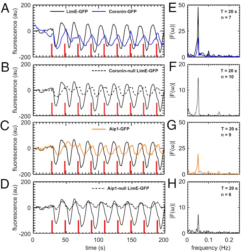
The rapid reorganization of the actin cytoskeleton in response to external stimuli is an essential property of many motile eukaryotic cells. Here, we report evidence that the actin machinery of chemotactic Dictyostelium cells operates close to an oscillatory instability. When averaging the actin response of many cells to a short pulse of the chemoattractant cAMP, we observed a transient accumulation of cortical actin reminiscent of a damped oscillation. At the single-cell level, however, the response dynamics ranged from short, strongly damped responses to slowly decaying, weakly damped oscillations. Furthermore, in a small subpopulation, we observed self-sustained oscillations in the cortical F-actin concentration. To substantiate that an oscillatory mechanism governs the actin dynamics in these cells, we systematically exposed a large number of cells to periodic pulse trains of different frequencies. Our results indicate a resonance peak at a stimulation period of around 20 s. We propose a delayed feedback model that explains our experimental findings based on a time-delay in the regulatory network of the actin system. To test the model, we performed stimulation experiments with cells that express GFP-tagged fusion proteins of Coronin and actin-interacting protein 1, as well as knockout mutants that lack Coronin and actin-interacting protein 1. These actin-binding proteins enhance the disassembly of actin filaments and thus allow us to estimate the delay time in the regulatory feedback loop. Based on this independent estimate, our model predicts an intrinsic period of 20 s, which agrees with the resonance observed in our periodic stimulation experiments.
Conflict of interest statement
The authors declare no conflict of interest.
Figures
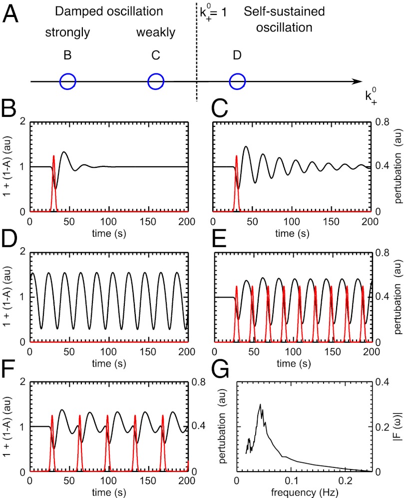
 and is marked by the dashed vertical line. The different response patterns displayed in Fig. 2 correspond to different values of the bifurcation parameter
  in the model. (B) Far from the bifurcation point
  , (C) close to the bifurcation point
  , and (D) beyond the bifurcation point in the oscillator regime
  . (E and F) Simulations of periodic stimulation with pulse trains of period T = 20 s (E) and T = 35 s (F),
  in both cases. (B–F) The red curves show the receptor stimulus, whereas the black curves show the evolution of the cortical actin concentration A(t) over time. For comparison with the experimental data, where the detrended cytosolic signal was displayed, we have plotted 1+(1−A). (G) Resonance curve for periodic stimuli ranging from T = 4–60 s. See Materials and Methods for details on how the receptor stimulus is incorporated into the model.
Similar articles
-
Microfilament dynamics during cell movement and chemotaxis monitored using a GFP-actin fusion protein.Curr Biol. 1997 Mar 1;7(3):176-83. doi: 10.1016/s0960-9822(97)70088-5. Curr Biol. 1997. PMID: 9276758
-
Chemoattractant-controlled accumulation of coronin at the leading edge of Dictyostelium cells monitored using a green fluorescent protein-coronin fusion protein.Curr Biol. 1995 Nov 1;5(11):1280-5. doi: 10.1016/s0960-9822(95)00254-5. Curr Biol. 1995. PMID: 8574585
-
Imaging actin cytoskeleton dynamics in Dictyostelium chemotaxis.Methods Mol Biol. 2009;571:385-400. doi: 10.1007/978-1-60761-198-1_26. Methods Mol Biol. 2009. PMID: 19763981
-
Structure/function studies on cytoskeletal proteins in Dictyostelium amoebae as a paradigm.FEBS Lett. 1995 Aug 1;369(1):38-42. doi: 10.1016/0014-5793(95)00579-x. FEBS Lett. 1995. PMID: 7641881 Review.
-
Streamer F mutants and chemotaxis of Dictyostelium.Bioessays. 1992 Jul;14(7):473-9. doi: 10.1002/bies.950140708. Bioessays. 1992. PMID: 1332700 Review.
Cited by
-
Rhythmicity and waves in the cortex of single cells.Philos Trans R Soc Lond B Biol Sci. 2018 May 26;373(1747):20170116. doi: 10.1098/rstb.2017.0116. Philos Trans R Soc Lond B Biol Sci. 2018. PMID: 29632268 Free PMC article. Review.
-
Screening by changes in stereotypical behavior during cell motility.Sci Rep. 2019 Jun 19;9(1):8784. doi: 10.1038/s41598-019-45305-w. Sci Rep. 2019. PMID: 31217532 Free PMC article.
-
Active oscillations in microscale navigation.Anim Cogn. 2023 Nov;26(6):1837-1850. doi: 10.1007/s10071-023-01819-5. Epub 2023 Sep 4. Anim Cogn. 2023. PMID: 37665482 Free PMC article. Review.
-
Moving towards a paradigm: common mechanisms of chemotactic signaling in Dictyostelium and mammalian leukocytes.Cell Mol Life Sci. 2014 Oct;71(19):3711-47. doi: 10.1007/s00018-014-1638-8. Epub 2014 May 21. Cell Mol Life Sci. 2014. PMID: 24846395 Free PMC article. Review.
-
Assessment of Dictyostelium discoideum Response to Acute Mechanical Stimulation.J Vis Exp. 2017 Nov 9;(129):56411. doi: 10.3791/56411. J Vis Exp. 2017. PMID: 29155792 Free PMC article.
References
-
- Van Haastert PJM, Devreotes PN. Chemotaxis: Signalling the way forward. Nat Rev Mol Cell Biol. 2004;5(8):626–634. - PubMed
-
- Kessin R. Dictyostelium: Evolution, Cell Biology, and the Development of Multicellularity. Cambridge, UK: Cambridge Univ Press; 2001.
-
- Annesley SJ, Fisher PR. Dictyostelium discoideum—A model for many reasons. Mol Cell Biochem. 2009;329(1-2):73–91. - PubMed
-
- McRobbie SJ, Newell PC. Changes in actin associated with the cytoskeleton following chemotactic stimulation of dictyostelium discoideum. Biochem Biophys Res Commun. 1983;115(1):351–359. - PubMed
Publication types
MeSH terms
Substances
LinkOut - more resources
Full Text Sources
Other Literature Sources
Molecular Biology Databases
Research Materials
