. 2014 Feb;71(2):846-52.
doi: 10.1002/mrm.24713.

Direct radiofrequency phase control in MRI by digital waveform playback at the Larmor frequency

Affiliations

Direct radiofrequency phase control in MRI by digital waveform playback at the Larmor frequency

Andrzej Jesmanowicz et al. Magn Reson Med. 2014 Feb.

Abstract

Purpose: A scalable multiband and multichannel digital magnetic resonance imaging system has been developed with the goal of reducing the time needed for acquisition of a single volume of gradient-recalled echo-planar images of the brain.

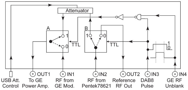
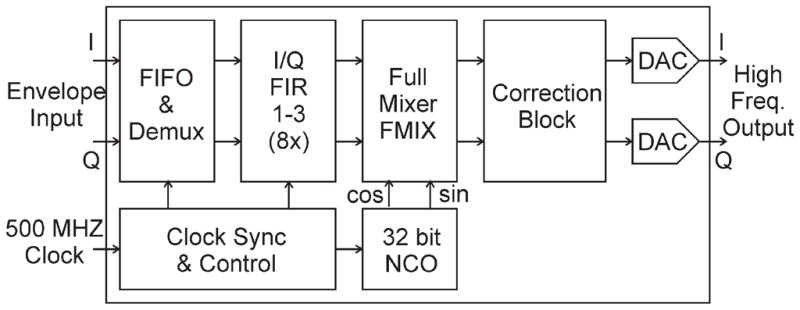
Methods: Transmit pulses are created by an offline computer equipped with a Pentek excitation card (PCIe model 78621) that was built around the Texas Instruments D/A converter (DAC5688).

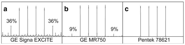
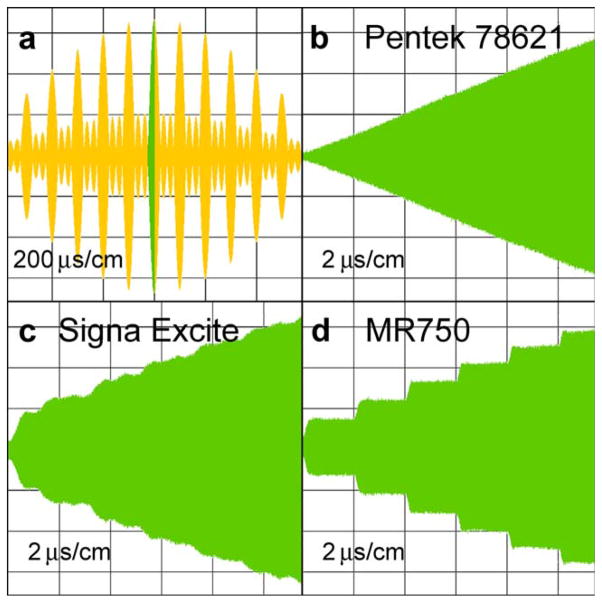
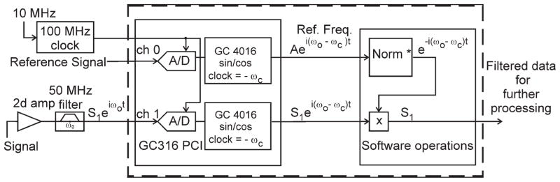
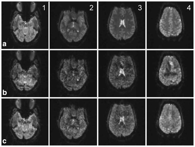
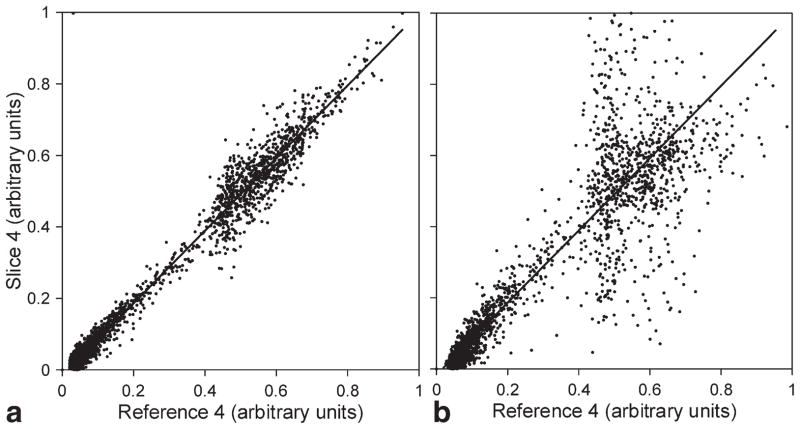
Results: The spectral purity of pulses made in this way surpasses the quality of pulses made by the standard modulators of the scanner, even when using the same pulse-creation algorithm. There is no need to mix reference waveforms with the magnetic resonance imaging signal to obtain inter-k-space coherency for different repetitions. The key was the use of a system clock to create the Larmor frequency used for pulse formation. The 3- and 4-fold slice accelerations were tested using phantoms as well as functional and resting-state magnetic resonance imaging of the human brain.

Conclusion: Synthesizers with limited modulation-time steps should be replaced not only because of the improved spectral quality of radiofrequency pulses but also for the exceptional coherence of pulses at different slice-selection frequencies.


Figures

FIG. 1
FIG. 1
Four-fold multiband spectral profiles created by: (a) the GE 3-T Signa EXCITE original modulator; (b) the GE 3-T MRI750 original modulator; and (c) the Pentek 78621 16-bit digital waveform synthesizer.
FIG. 2
FIG. 2
Oscillograms of RF pulses obtained by different modulators: (a) the central region of a 6.4-ms long RF pulse at a resolution of 200 μs/cm. The 12-μs segment marked by green is expanded in other windows at a resolution of 2 μs/cm; (b) an envelope created by the Pentek 78621 16-bit digital waveform synthesizer; (c) an envelope created by the GE 3-T Signa EXCITE original modulator; and (d) an envelope created by the GE 3-T MRI750 original modulator.
FIG. 3
FIG. 3
The switching box diagram directing different RF pulses to the RF power transmitter. Output OUT2 is used as a source of the reference signal created by the Pentek 78621 16-bit digital waveform synthesizer.
FIG. 4
FIG. 4
Configuration of the off-line acquisition system.
FIG. 5
FIG. 5
The RF track of the DAC5688 chip. The figure is an excerpt from the Texas Instruments manual for 16-bit, dual-channel, interpolating digital-to-analog converter DAC5688.
FIG. 6
FIG. 6
Phase images obtained by a conventional gradient-echo method at a resolution of 256 × 256: (a) coronal image created from the set of 31 axial slices using the GE 3-T Signa EXCITE original modulator showing no phase coherency; (b) coronal image created from the set of 31 axial slices using the Pentek 78621 16-bit digital waveform synthesizer. Interslice coherence is evident; (c) example of a single axial phase image used to construct the coronal cross sections in (a) and (b).
FIG. 7
FIG. 7
Four slices, 1-mm thick, spaced by 20 mm, were placed to allow for incidental excitation of two ghost slices in the lower and upper parts of the brain. Row (a) shows four reference slices 1–4. Row (b) shows separated slices that were excited using the GE 3-T Signa EXCITE original modulator. Row (c) shows separated slices that were excited using the Pentek 78621 16-bit digital waveform synthesizer. On the separated image (b4), there is an explicitly visible interference pattern of the size and shape of the first top ghost slice that was created using the GE 3-T Signa EXCITE modulator. The Pentek synthesizer does not create ghosts and therefore the equivalent slice (c4) is clean and resembles the reference slice (a4).
FIG. 8
FIG. 8
Scatter plots of corresponding voxel signal intensities of the separated slice 4 of the first image of the EPI series and the equivalent reference slice. Graphs: (a) plot for the slice created by the Pentek 78621 16-bit digital waveform synthesizer and (b) plot for the slice created by the GE 3-T Signa EXCITE modulator.

References

    1. Jesmanowicz A, Li S-J, Hyde JS. Multi-slice two- and four-fold acceleration with single- and eight-channel coils, respectively [abstract]. Proceedings of the 17th Annual Meeting of ISMRM; Honolulu, Hawaii, USA. 2009. p. 1089.
    1. Jesmanowicz A, Nencka AS, Li S-J, Hyde JS. Two-axis acceleration of functional connectivity magnetic resonance imaging by parallel excitation of phase-tagged slices and half k-space acceleration. Brain Connect. 2011;1:81–90. - PMC - PubMed
    1. Moeller S, Yacoub E, Olman CA, Auerbach E, Strupp J, Harel N, Ugurbil K. Multiband multislice GE-EPI at 7 Tesla, with 16-fold acceleration using partial parallel imaging with application to high spatial and temporal whole-brain fMRI. Magn Reson Med. 2010;63:1144–1153. - PMC - PubMed
    1. Feinberg DA, Moeller S, Smith SM, Auerbach E, Ramanna S, Glasser MF, Miller KL, Ugurbil K, Yacoub E. Multiplexed echo planar imaging for sub-second whole brain fMRI and fast diffusion imaging. PLoS One. 2010;5:e15710. - PMC - PubMed
    1. Larkman DJ, Hajnal JV, Herlihy AH, Coutts GA, Young IR, Ehnholm G. Use of multicoil arrays for separation of signal from multiple slices simultaneously excited. J Magn Reson Imaging. 2001;13:313–317. - PubMed

Publication types