. 2013 Mar;21(2):319-28.
doi: 10.1109/TNSRE.2013.2245423.

Safe direct current stimulation to expand capabilities of neural prostheses

Affiliations

Safe direct current stimulation to expand capabilities of neural prostheses

Gene Y Fridman et al. IEEE Trans Neural Syst Rehabil Eng. 2013 Mar.

Abstract

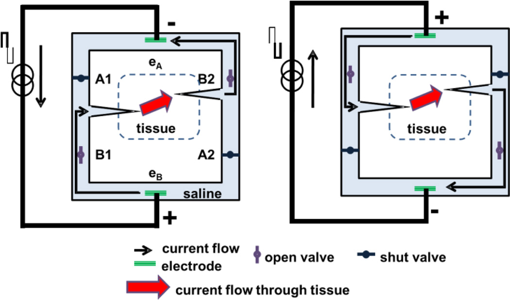
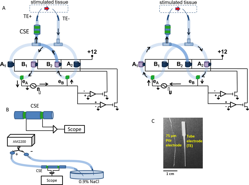
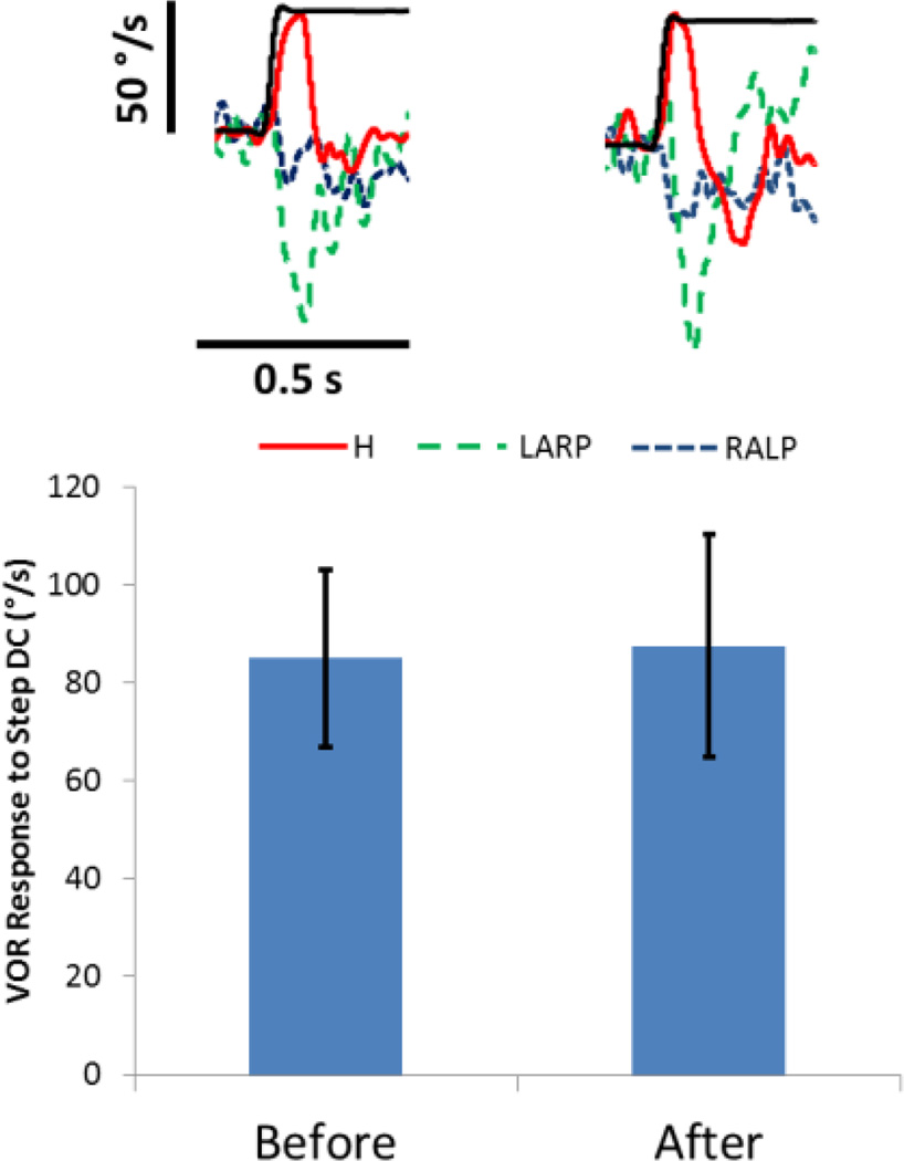
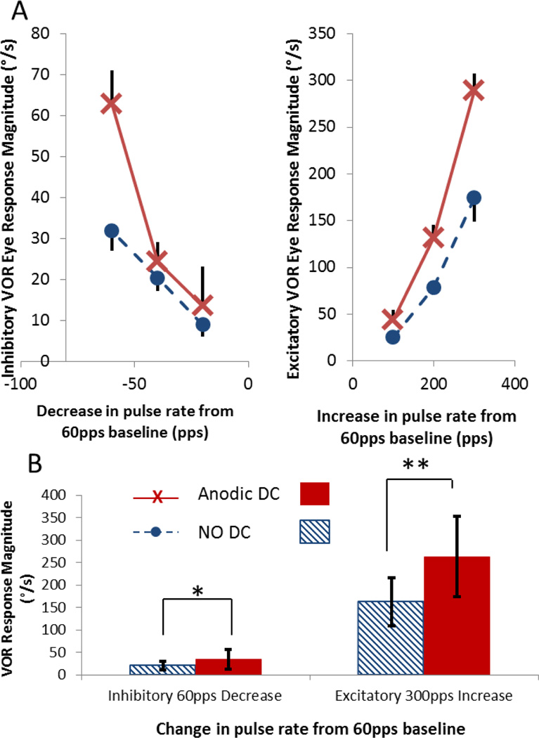
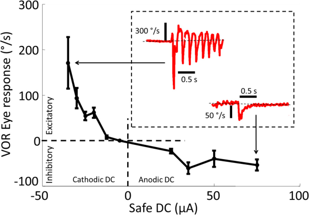
While effective in treating some neurological disorders, neuroelectric prostheses are fundamentally limited because they must employ charge-balanced stimuli to avoid evolution of irreversible electrochemical reactions and their byproducts at the interface between metal electrodes and body fluids. Charge-balancing is typically achieved by using brief biphasic alternating current (AC) pulses, which typically excite nearby neural tissues but cannot efficiently inhibit them. In contrast, direct current (DC) applied via a metal electrode in contact with body fluids can excite, inhibit and modulate sensitivity of neurons; however, chronic DC stimulation is incompatible with biology because it violates charge injection limits that have long been considered unavoidable. In this paper, we describe the design and fabrication of a Safe DC Stimulator (SDCS) that overcomes this constraint. The SCDS drives DC ionic current into target tissue via salt-bridge micropipette electrodes by switching valves in phase with AC square waves applied to metal electrodes contained within the device. This approach achieves DC ionic flow through tissue while still adhering to charge-balancing constraints at each electrode-saline interface. We show the SDCS's ability to both inhibit and excite neural activity to achieve improved dynamic range during prosthetic stimulation of the vestibular part of the inner ear in chinchillas.


Conflict of interest statement

The terms of these arrangements are being managed by the Johns Hopkins University in accordance with its conflict of interest policies.

Figures

Figure 1
Figure 1
SDCS concept. The two panels represent two states of the same device. (Left) Current flows from the lower electrode to the upper electrode. (Right) Current reverses direction, but because valves change state along with the electrical current direction, the ionic DC current (indicated by thick red arrow) still flows through the electrode tubes from left to right through the tissue. Valve A1 is always in the same state as valve A2 and valve B1 is always in the same state as valve B2, and all switch in synchrony with changes in electrode polarity.
Figure 2
Figure 2
SDCS1 prototype. (A) Two states of the system analogous to the schematic in Fig 1 are shown. Arrows indicate electric current flow. Open valves are light purple and shut valves are dark blue. The two tube electrodes (TE+ and TE−) deliver current to the tissue in the same direction in both system states indicated by the red arrow. Valves are interconnected with surgical tubing filled with 0.9% NaCl solution. Circuit at bottom right detects electrode voltage polarity and synchronously opens and closes valves in response to a square-wave AC signal is applied to electrodes eA and eB. (B) The output current is monitored using the CSE which differentially senses the voltage between two metal electrodes in contact with an ionic gel-filled salt bridge. The diagram shows calibration setup with tube electrodes, but calibration was also conducted with just surgical tubing inserted into the petri dish. AM2200 delivers controlled constant current via large surface area electrodes through the CSE and the voltage across the sensing electrodes is recorded with the scope. (C) Tube electrodes filled with ionic gel conduct ionic current from the SDCS but resist biological contamination and fluid flow, shown here in comparison with a twisted pair of 75µm PtIr wire electrodes commonly used for neural stimulation animal experiments.
Figure 3
Figure 3
SDCS1 bench tests. (A) CSE Calibration curve. (N=4) voltage-current relationship of the CSE did not change when tube electrodes were used at the output of the device instead of low impedance large diameter surgical tubing. (B) SDCS1 system output as measured by CSE is near 0 when all valves are closed. Current amplitude bar and time bar applies to B, C and D (C) Current flows in both directions when A valves are open and B valves are shut. (D) Approximately DC current when the valve driver circuit operates normally. Interruptions of output current flow due to non-ideal nature of the mechanical valve operation are apparent (one is within the oval). Interruptions are 10–50 ms long.
Figure 4
Figure 4
Long term stimulation with 80uA safe DC current delivered via tube electrodes. An active tube electrode was implanted in the horizontal semicircular canal and a return tube electrode was implanted in the vestibule. Individual VOR responses show the three spatial components (red solid=Horizontal, green dashed =right anterior/left posterior, blue dotted = right anterior/left posterior) of the 3D VOR response to onset of a 80µA step in anodic DC (thin black) before (left) and after (right) the 15000s of 80µA anodic DC. The bar graph indicates the VOR responses to the 1s anodic DC test stimuli obtained before and after the 15000s of continual DC stimulation. VOR response amplitude and axis did not change significantly (P>0.63 for each, N=5) after delivering DC for 15000s through tube electrodes.
Figure 5
Figure 5
VOR responses to steps in PFM when anodic DC is used to suppress the vestibular nerve are greater than for PFM alone. (A) VOR responses of chinchilla ch408 to decreasing (left plot) and increasing (right plot) steps in rate from 60pps baseline. (B) Aggregated VOR responses from all three chinchillas. Responses to the maximum decrease (right) and increase (left) in pulse rates are shown. Solid bars show VOR magnitude during combined DC and steps of PFM. Striped bars show VOR magnitude for PFM steps alone. When animals were stimulated with DC+PFM, a step decrease in pulse rate from 60pps to 0pps elicited significantly greater inhibitory responses (*,ANOVA F=25, P<0.03), and a step increase in pulse rate from 60 pps to 300pps elicited significantly greater excitatory responses (**, ANOVA F=334, P<10−6).
Figure 6
Figure 6
VOR responses of chinchilla ch406 to steps of safe DC delivered using the SCDS1 stimulator connected to a perilymphatic tube electrode and distant reference in neck musculature. Positive current is anodic at the active electrode. Positive eye velocity is rightward and consistent with excitation of the implanted left labyrinth. Anodic DC evokes eye responses consistent with nerve inhibition; cathodic DC evokes responses consistent with nerve excitation. As expected, maximal inhibitory VOR responses are ~1/3 of maximal excitatory responses. Brief leftward spikes interrupting the response to cathodic DC are nystagmus quick phases, non-VOR movements that reset eye position when the eyes approach extremes of their range of motion.

References

    1. Guenther T, Lovell NH, Suaning GJ. Bionic vision: system architectures: a review. Expert. Rev. Med. Devices. 2012 Jan.9(no. 1):33–48. - PubMed
    1. Wilson BS, Dorman MF. Cochlear implants: a remarkable past and a brilliant future. Hear. Res. 2008 Aug.242(no. 1–2):3–21. - PMC - PubMed
    1. Merrill DR, Bikson M, Jefferys JGR. Electrical stimulation of excitable tissue: design of efficacious and safe protocols. Journal of Neuroscience Methods. 2005;141(no. 2) - PubMed
    1. Robblee L, Rose T. Electrochemical guidelines for selection of protocols and electrode materials for neural stimulation. In: McCreary DB, Agnew WF, editors. Neural Prostheses: Fundamental Studies. Prentice-Hall; 2003.
    1. Rose TL, Robblee LS. Electrical-Stimulation with Pt Electrodes .8. Electrochemically Safe Charge Injection Limits with 0.2 Ms Pulses. IEEE Transactions on Biomedical Engineering. 1990;37(no. 11) - PubMed

Publication types