. 2013 Jun 11;29(23):7070-8.
doi: 10.1021/la400747y. Epub 2013 Apr 4.

Maneuvering the internal porosity and surface morphology of electrospun polystyrene yarns by controlling the solvent and relative humidity

Affiliations

Maneuvering the internal porosity and surface morphology of electrospun polystyrene yarns by controlling the solvent and relative humidity

Ping Lu et al. Langmuir. .

Abstract

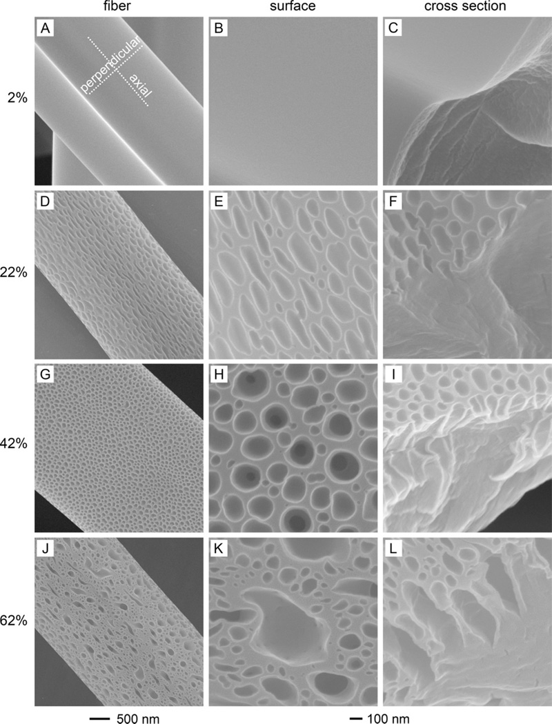
This article presents a simple and reliable method for generating polystyrene (PS) yarns composed of bundles of nanofibrils by using a proper combination of solvent and relative humidity. We elucidated the mechanism responsible for the formation of this new morphology by systematically investigating the molecular interactions among the polymer, solvent(s), and water vapor. We demonstrated that vapor-induced phase separation played a pivotal role in generating the yarns with a unique structure. Furthermore, we discovered that the low vapor pressure of N,N-dimethylformamide (DMF) was critical to the evolution of pores in the interiors. On the contrary, the relatively high vapor pressure of tetrahydrofuran (THF) hindered the formation of interior pores but excelled in creating a rough surface. In all cases, our results clearly indicate that the formation of either internal porosity or surface roughness required the presence of water vapor, a nonsolvent of the polymer, at a proper level of relative humidity. The exact morphology or pore structure was dependent on the speed of evaporation of the solvent(s) (DMF, THF, and their mixtures) as well as the interdiffusion and penetration of the nonsolvent (water) and solvent(s). Our findings can serve as guidelines for the preparation of fibers with desired porosity both internally and externally through electrospinning.


Figures

Figure 1
Figure 1
SEM images showing the yarns of PS nanofibers electrospun from a 20 wt.% PS solution in DMF at 20 °C and under relative humidity of 52% (voltage: 15 kV; feeding rate: 1 mL/h; and needle-collector distance: 25 cm). The as-spun yarns showed (A) good uniformity throughout the mat, (B) smooth surfaces on individual yarns, and (C, D) an inherently porous structure in the interior, with nanofibrils being aligned parallel to the long axis of each yarn.
Figure 2
Figure 2
Comparison of the surfaces (left panel) and cross sections (right panel) of PS fibers/yarns fabricated by electrospinning a 20 wt.% PS solution in DMF under different relative humidity: (A, B) 2%, (C, D) 22%, (E, F) 42%, and (G, H) 62% (voltage: 15 kV; feeding rate: 1 mL/h; needle-collector distance: 25 cm; and temperature: 20 °C). The scale bar in (H) applies to all other images.
Figure 3
Figure 3
Representative PS fibers with pores on the surfaces (left panel) and their corresponding surfaces (middle panel) and cross sections (right panel) fabricated by electrospinning a 20 wt.% PS solution in THF under different relative humidity: (A, B, C) 2%, (D, E, F) 22%, (G, H, I) 42%, and (J, K, L) 62% (voltage: 15 kV; feeding rate: 1 mL/h; needle-collector distance: 25 cm; and temperature: 20 °C). The 500 nm scale bar applies to the images in the left panel while the 100 nm scale bar applies to the middle and right panels.
Figure 4
Figure 4
SEM images showing PS fibers (left panel) and the corresponding surfaces (middle panel) and cross sections (right panel) by electrospinning a 20 wt.% PS solution in DMF/THF (1:1 w:w) at different relative humidity: (A, B, C) 2%, (D, E, F) 22%, (G, H, I) 42%, and (J, K, L) 62% (voltage: 15 kV; feeding rate: 1 mL/h; needle-collector distance: 25 cm; and temperature: 20 °C). The 500 nm scale bar applies to the left panel images and 100 nm to the middle and right panel ones.
Figure 5
Figure 5
A schematic illustration detailing the structural characteristics at different stages of an electrospinning process: (1) immediately after ejection from the needle, (2) during whipping and stretching, and (3) upon drying on the collector. The electrospinning was conducted at (B) low relative humidity (2%) and (C) high relative humidity (42% and 62%). The blue, green, and gray colors represent water (vapor), DMF, and solidified PS, respectively. The intensity of green color corresponds to the gradually decreased DMF concentrations from center of the yarn to its outer surface while the white and grey drawings indicate no DMF remaining. The arrows indicate the diffusion directions of the liquid. The presence of solid lines at two sides of the yarn (grey) in (C) refers to the formation of a mechanically strong sheath. The drawing only shows the trend of reduction in size for the yarn but not proportional to the actual scales.
Figure 6
Figure 6
A diagram illustrating the changes to structural characteristics at positions of (1) immediately after ejection from the needle, (2) during whipping and stretching, and (3) upon drying on the collector from electrospinning conducted at (A) low relative humidity (2%) and (B) high relative humidity (22%, 42%, and 62%). The blue, red, and grey colors represent water, THF, and solidified PS, respectively. The intensity of red color corresponds to the concentration of THF while the grey drawing indicates no THF remaining. The blue spheres refer to the condensed water vapor in the form of tiny droplets which should not be deemed as the actual size relative to the PS fiber. The arrows indicate the diffusion directions of the liquid. The drawing only shows the trend of reduction in size for the fiber but not proportional to the actual scales.
Figure 7
Figure 7
SEM images showing (A) a PS fiber with nano-pillars on the surface and (B) enlarged area boxed in (A). The electrospinning was conducted with a 20 wt.% PS solution in DMF/THF (1:1 w:w) under relative humidity of 22% (voltage: 15 kV; feeding rate: 1 mL/h; needle-collector distance: 25 cm; and temperature: 20 °C).
Figure 8
Figure 8
A schematic showing the formation mechanism of PS yarns with nano-pillars on the surface, as well as structural changes to the jet at different positions: (1) immediately after ejection from the needle, (2) during whipping and stretching, and (3) upon drying on the collector. The electrospinning was conducted with a 20 wt.% PS solution in DMF/THF (w:w 1:1) at high relative humidity (62%). The intensities of the green and red colors correspond to the amounts of DMF and THF inside the liquid jet while the white and grey drawings indicate no residual DMF and THF. The blue spheres refer to the condensed water moisture in the form of tiny droplets which should not be deemed as the actual size relative to the PS yarn. The arrows indicate the diffusion directions of the liquid. The presence of solid lines at two sides of the yarn (grey) refers to the formation of a mechanically strong sheath. The drawing only shows the trend of reduction in size for the yarn but not proportional to the actual scales.

References

    1. Dawson R, Cooper AI, Adams DJ. Nanoporous organic polymer networks. Prog. Polym. Sci. 2012;37:530–563.
    1. Tsioptsias C, Stefopoulos A, Kokkinomalis I, Papadopoulou L, Panayiotou C. Development of micro- and nano-porous composite materials by processing cellulose with ionic liquids and supercritical CO2. Green Chemistry. 2008;10:965–971.
    1. Yang SY, Ryu I, Kim HY, Kim JK, Jang SK, Russell TP. Nanoporous Membranes with Ultrahigh Selectivity and Flux for the Filtration of Viruses. Adv. Mater. 2006;18:709–712.
    1. Cooper AI. Nanoporous Organics Enter the Cage Age. Angew. Chem. Int. d. 2011;50:996–998. - PubMed
    1. Colombo P. In Praise of Pores. Science. 2008;322:381–383. - PubMed

Publication types