

Dynamic self-stiffening in liquid crystal elastomers
- PMID: 23612280
- PMCID: PMC3648875
- DOI: 10.1038/ncomms2772
Dynamic self-stiffening in liquid crystal elastomers
Abstract
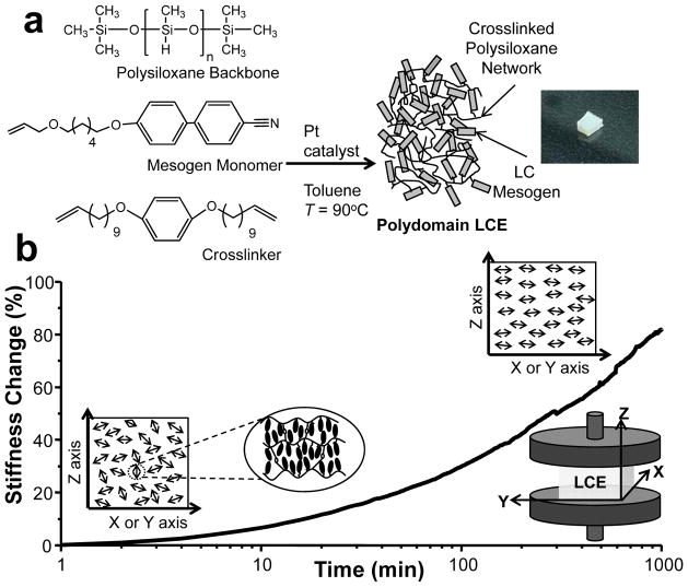
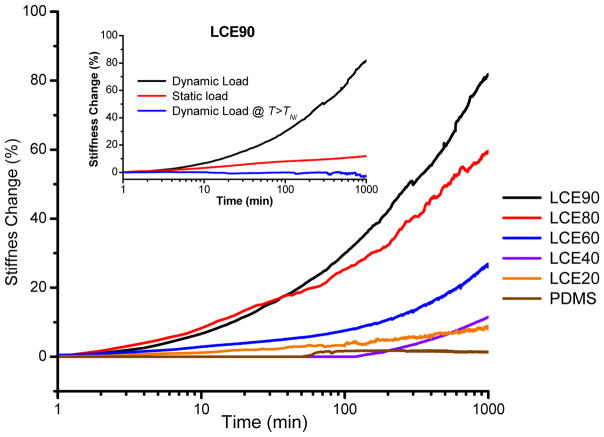
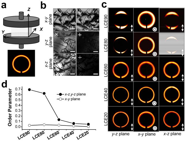
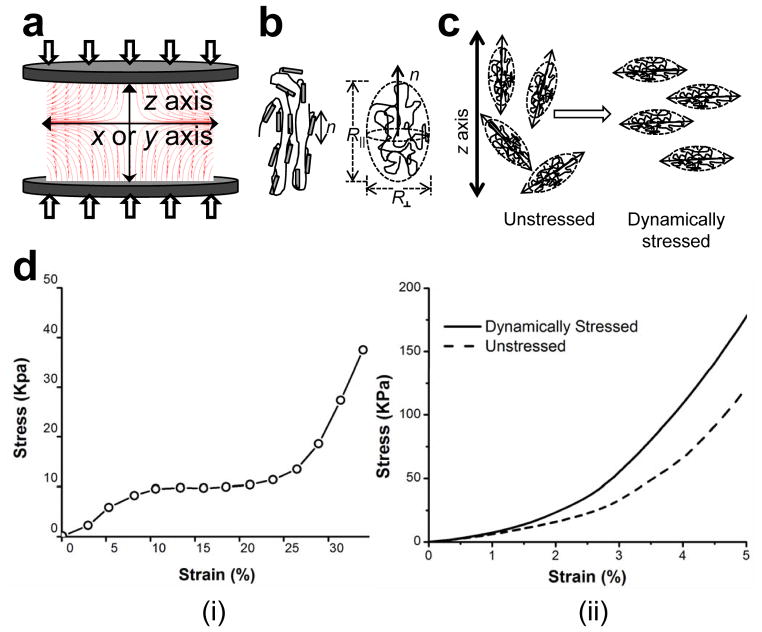
Biological tissues have the remarkable ability to remodel and repair in response to disease, injury and mechanical stresses. Synthetic materials lack the complexity of biological tissues, and man-made materials that respond to external stresses through a permanent increase in stiffness are uncommon. Here we report that polydomain nematic liquid crystal elastomers increase in stiffness by up to 90% when subjected to a low-amplitude (5%), repetitive (dynamic) compression. Elastomer stiffening is influenced by liquid crystal content, the presence of a nematic liquid crystal phase and the use of a dynamic as opposed to static deformation. Through rheological and X-ray diffraction measurements, stiffening can be attributed to a mobile nematic director, which rotates in response to dynamic compression. Stiffening under dynamic compression has not been previously observed in liquid crystal elastomers and may be useful for the development of self-healing materials or for the development of biocompatible, adaptive materials for tissue replacement.
Conflict of interest statement
The authors declare no competing financial interests.
Figures
Similar articles
-
Thermoresponsive inverse opal films fabricated with liquid-crystal elastomers and nematic liquid crystals.Langmuir. 2011 Feb 15;27(4):1505-9. doi: 10.1021/la1037124. Epub 2010 Nov 30. Langmuir. 2011. PMID: 21117652
-
Optical mechanotransduction with carbazole-based luminescent liquid single-crystal elastomers.Macromol Rapid Commun. 2015 Apr;36(8):755-61. doi: 10.1002/marc.201400734. Epub 2015 Feb 19. Macromol Rapid Commun. 2015. PMID: 25704537
-
Effects of Structural Variations on the Cellular Response and Mechanical Properties of Biocompatible, Biodegradable, and Porous Smectic Liquid Crystal Elastomers.Macromol Biosci. 2017 Feb;17(2). doi: 10.1002/mabi.201600278. Epub 2016 Nov 2. Macromol Biosci. 2017. PMID: 27805765
-
Recent progress in dynamic covalent chemistries for liquid crystal elastomers.J Mater Chem B. 2020 Aug 12;8(31):6610-6623. doi: 10.1039/d0tb00754d. J Mater Chem B. 2020. PMID: 32555841 Review.
-
Functional Liquid Crystal Elastomers Based on Dynamic Covalent Chemistry.Chemistry. 2022 Dec 15;28(70):e202201957. doi: 10.1002/chem.202201957. Epub 2022 Oct 13. Chemistry. 2022. PMID: 36046951 Review.
Cited by
-
A pseudo-anelastic model for stress softening in liquid crystal elastomers.Proc Math Phys Eng Sci. 2020 Nov;476(2243):20200558. doi: 10.1098/rspa.2020.0558. Epub 2020 Nov 4. Proc Math Phys Eng Sci. 2020. PMID: 33362420 Free PMC article.
-
Visible and infrared three-wavelength modulated multi-directional actuators.Nat Commun. 2019 Oct 4;10(1):4539. doi: 10.1038/s41467-019-12583-x. Nat Commun. 2019. PMID: 31586123 Free PMC article.
-
Training and retraining liquid crystal elastomer metamaterials for pluripotent functionality.Proc Natl Acad Sci U S A. 2025 Jul 22;122(29):e2504304122. doi: 10.1073/pnas.2504304122. Epub 2025 Jul 16. Proc Natl Acad Sci U S A. 2025. PMID: 40668827
-
Structural basis for the nonlinear mechanics of fibrin networks under compression.Biomaterials. 2014 Aug;35(25):6739-49. doi: 10.1016/j.biomaterials.2014.04.056. Epub 2014 May 16. Biomaterials. 2014. PMID: 24840618 Free PMC article.
-
Preparation of Monodomain Liquid Crystal Elastomers and Liquid Crystal Elastomer Nanocomposites.J Vis Exp. 2016 Feb 6;(108):e53688. doi: 10.3791/53688. J Vis Exp. 2016. PMID: 26889665 Free PMC article.
References
-
- Fung YC. Biomechanics: Mechanical Properties of Living Tissues. 2. Springer; New York: 1993.
-
- Jones GW, Chapman SJ. Modeling growth in biological materials. Siam Rev. 2012;54:52–118.
-
- Humphrey JD. Review Paper: Continuum biomechanics of soft biological tissues. R Soc Lond Proc Ser A Math Phys Eng Sci. 2003;459:3–46.
-
- Cowin SC. Bone Mechanics Handbook. 2. CRC Press; Boca Raton: 2001.
-
- Helmlinger G, Netti PA, Lichtenbeld HC, Melder RJ, Jain RK. Solid stress inhibits the growth of multicellular tumor spheroids. Nat Biotechnol. 1997;15:778–783. - PubMed
Publication types
MeSH terms
Substances
Grants and funding
LinkOut - more resources
Full Text Sources
Other Literature Sources
