. 2013 Jul;99(7):448-59.
doi: 10.1002/bip.22199.

Domain organization of membrane-bound factor VIII

Affiliations

Domain organization of membrane-bound factor VIII

Svetla Stoilova-McPhie et al. Biopolymers. 2013 Jul.

Abstract

Factor VIII (FVIII) is the blood coagulation protein which when defective or deficient causes for hemophilia A, a severe hereditary bleeding disorder. Activated FVIII (FVIIIa) is the cofactor to the serine protease factor IXa (FIXa) within the membrane-bound Tenase complex, responsible for amplifying its proteolytic activity more than 100,000 times, necessary for normal clot formation. FVIII is composed of two noncovalently linked peptide chains: a light chain (LC) holding the membrane interaction sites and a heavy chain (HC) holding the main FIXa interaction sites. The interplay between the light and heavy chains (HCs) in the membrane-bound state is critical for the biological efficiency of FVIII. Here, we present our cryo-electron microscopy (EM) and structure analysis studies of human FVIII-LC, when helically assembled onto negatively charged single lipid bilayer nanotubes. The resolved FVIII-LC membrane-bound structure supports aspects of our previously proposed FVIII structure from membrane-bound two-dimensional (2D) crystals, such as only the C2 domain interacts directly with the membrane. The LC is oriented differently in the FVIII membrane-bound helical and 2D crystal structures based on EM data, and the existing X-ray structures. This flexibility of the FVIII-LC domain organization in different states is discussed in the light of the FVIIIa-FIXa complex assembly and function.


Figures

FIGURE 1
FIGURE 1
FVIII primary structure. FVIII single chain: the FVIII domains A1, A2, A3, B, C1, and C2 linear arrangement and amino acid numbering are shown. The acidic domains crucial for FVIII proteolytic activation are denoted as a1, a2, and a3. The main interactions sites with other coagulation factors: X, Xa, IXa, von Wlbrandt factor (vWF), and phospholipids (PL) are indicated with rectangular boxes, as well as the corresponding amino acid numbering. FVIII heterodimer: the gray arrows show the thrombin cleavage sites. The divalent metal ions (Me2+) holding the heavy chain (HC) and light chain (LC) are indicated with a dark ellipse. FVIIIa heterotrimer: the FVIII heterotrimer is held together by additional hydrophobic and electrostatic interactions between the A1 and A2 domains from the HC, shown as black dashed lines. SDS-PAA gel of the recombinant FVIII full length variant utilized in this study, which is identical to the plasma-derived FVIII utilized in the 2D crystals study. FVIII-FL exists as a mixture of heterodimers with a constant LC of ~80 kDa molecular weight and variable HCs (90–200 kDa). The standards are indicated with S. 1-indicated the protein in the presence of 5 mM Ca2+ and with 2-the protein in the presence of 20 mM EDTA showing that the LC remains intact after treatment with 20 mM EDTA.
FIGURE 2
FIGURE 2
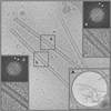
Digital cryo-EM micrograph of FVIII-LC–LNT (4096 × 4096 pixels at 2.9 Å/pixel). The inner tubes’ diameter is 190 Å. The length varies from 0.5 µm to a few micrometer. (a and b white) Fourier transforms (FTs) and inverse FT of the 512 × 512 pixel boxed area are denoted with a gray dashed line (a and b black). The two visible layer lines on the FT are centered at 0.0083 Å−1 and 0.0167 Å−1 (white arrows), respectively. The defocus of the images included in the dataset is between −0.7 µm and −4.4 µm, as calculated from the first Thon ring of the FT of the individual images with an overall average value of −2.5 ± 1.2 µm. (A) Low-magnification view of FVIII-LC–LNT. The FVIII-LC–LNT are frozen hydrated in amorphous ice over 2 µm diameter holes spaced 2 µm. The lipid and protein densities are in black.
FIGURE 3
FIGURE 3. 2D analysis of FVIII-LC–LNT
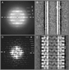
A. Combined FT from 2043 FVIII-LC–LNT helical segments (particles). The layer lines are indicated as 1—1/120 Å−1, 2—1/60 Å1, and 3—1/40 Å−1. The equator is indicated with a white dashed line. (B) Representative 2D class average from 277 control LNT (cLNT) segments with the same lipid composition as in (C) (Supporting Information 1). The lipid bilayer is well defined. The inner and outer leaflet and the lower density of the membrane hydrophobic core are clearly visible. The circle (white dashed line, 75 Å diameter) indicates the lipid bilayer. The inner diameter of the cLNT is 175 Å. (C) Representative 2D class average from 184 FVIII-LC–LNT particles (Supporting Information 1). The inner diameter of the FVIII-LC–LNT is 190 Å. The oval (white dashed line, 115 Å × 75 Å) indicates the 2D-projected density of the FVIII-LC-molecules oriented orthogonally to the lipid bilayer. The 2D class averages in (B) and (C) are cropped to 240 × 240 pixels at 2.9 Å/pixel. (D) FT of (C) showing up to eight layer lines (8—1/15 Å). The equator is indicated with a white dashed line. (A) and (D) are cropped views of the full FT of the helical segments.
FIGURE 4
FIGURE 4
3D reconstruction of FVIII-LC-LNT. (A) Orthorhombic view along the long LNT axis (z-axis). The solid surface is contoured at 0.005 density level and viewed at 5.8 Å/pixel resolution in Chimera—volume viewer option. The surface is colored as follows (radius of outer shell from center): red—114 Å and yellow—162 Å are the densities corresponding to the LNT bilayer (red is the inner membrane layer). The FVIII-LC membrane-binding part is colored in green—198 Å and the FVIII-LC part not involved in the membrane binding is in magenta—250 Å. The tube inner diameter is 190 Å and the outer diameter 500 Å. The density corresponding to a cLNT is shown with red and yellow mesh (2.9 Å mesh size) contoured at 0.05 threshold with the same radii as for the FVIII-LC-LNT. (B) View rotated 45° and (C) 90° counterclockwise from (A) around the z-axis. The length of the tube corresponds to the boxed FVIII-LC-LNT segments: 256 pixels (2.9 Å/pixel) equal to ~12 turns of the FVIII-LC helix around the LNT, as the symmetry of the FVIII-LC-LNT helix is 7.5 subunits (FVIII-LC) molecules per turn (pitch = 60 Å = 20.7 pixels).
FIGURE 5
FIGURE 5
FVIII domain organization in 2D and 3D crystals. (A) Domain organization of FVIII in 3D crystals as solved by X-ray crystallography (3CDZ). In the FVIII-3D structure two N-acetyl glucosamines: Nag2334 and Nag2335 (dark and light gray spheres) and three manose residues: Man2336–2338 (light gray spheres) are in close proximity to Asn2118 (green spheres) at the C1–A3 interface., (B) Domain organization of FVIII in 2D crystals as proposed by EM. In the FVIII-2D structure the Asn2118 is moved to the C1–A1 interface, due to the rearrangement of the C domains respective to the 3A domain in the 2D crystal structure. The Nag2334 (dark gray spheres) is also moved with the Asn2118 to the C1–A1 interface and is stabilized additionally by Arg121 (blue spheres) from the A1 domain and Asn2141 (light blue spheres) from the C1 domain. The NAG2335 (light gray spheres) remains at the C1–A3 interface in proximity to Gln1938 (aquamarine spheres) and Thr1872 (light green spheres) from the A3 domains, as originally resolved in the FVIII-3D structure. The FVIII structures in (A) and (B) are aligned on the 3A domains, as previously shown. (C) Magnified view of the C—A domains interface. Top: C1–A3 and C2–A1 domains interface in the FVIII-3D structure and bottom: C1–A3 and C1–A1 interface in the FVIII-2D structure. The A1 domain is colored blue, the A3 orange, the C1 magenta, and the C2 red. In the FVIII-3D structure, the Nag2335 at the C1–A3 interface (top) is in proximity to three mannose residues (Man 2336, 2337, and 2338 light gray spheres). We cannot assert at this point whether the mannose residues and NAG2335 remain at the C1–A3, as resolved in the FVIII-X-ray structure.
FIGURE 6
FIGURE 6
Fitting of the FVIII-LC within the FVIII-LC–LNT protein–membrane density defined by cryo-EM. (A) Surface representation of half of the FVIII-LC–LNT 3D density map calculated from the cryo-EM data, drawn at 2.9 Å/pix and 0.004 contour level. The FVIII-LC-3D (blue), the FVIII-LC-2D (red), and the FVIII-LC–LNT (green) structures are shown as surfaces and fitted with the “fit in map” option of UCSF Chimera (Supporting Information 3, Table I). The density corresponding to the cLNT membrane is shown in orange. The orthogonal fitting of the FVIII-LC-3D structures is not allowed as it interferes with the density of the adjacent molecule as seen in (B). (B) Combined surface and solid density maps of two adjacent FVIII-LC–LNT molecules. In red is the density corresponding to 0.019 thresholds and in yellow to 0.009 (map density: min = 0.0, max = 0.02). The FVIII-LC-3D (red), FVIII-LC-2D (blue), and FVIII-LC–LNT (green) structures are fitted as in (A). Phe2200 and Leu2252 from the C2 domain hairpin loops interacting directly with the membrane are shown with orange spheres.
FIGURE 7
FIGURE 7
FVIII membrane-bound organizations. (A) FVIII-3D structure calculated from X-ray (3CDZ) oriented following the identified C2 and C1 membrane-binding residues. (B) FVIII-2D structure calculated from EM of membrane-bound FVIII-2D crystals. (C) FVIII–LNT structure calculated from helically assembled FVIII-LC onto LNT. The FVIIII domains are colored as follows: A1—yellow, A2—red, A3—green, C1—magenta, and C2—cyan. The C2 domains membrane-binding residues interacting directly with the membrane: Val2223, His2315, Met2199-Phe2200, and Leu2251–2252 are shown as orange spheres. (A) The C1 amino acid residues from the FVIII-3D structure interacting directly with the membrane: Ile2059 and Lys2092–Phe2093 are shown as orange spheres. The Factor IXa-binding loops A2: 558–565, 702–721 and A3: 1811–1818 are shown in purple and the critical residues for the FVIIIa–FIXa-binding interface: Lys1818, Lys713, and Arg562 are shown as purple spheres. The C1: Cys2021, Cys 2169 and the C2: Cys2174, Cys2326 residues forming disulfide bonds are shown in dark blue. The LC/membrane and HC/LC interfaces are shown as green and blue rectangles, respectively.

Similar articles

Cited by

References

    1. Toole JJ, Knopf JL, et al. Nature. 1984;312:342–347. - PubMed
    1. Vehar GA, Keyt B, et al. Nature. 1984;312:337–342. - PubMed
    1. Kane WH, Davie EW. Blood. 1988;71:539–555. - PubMed
    1. Lenting PJ, Mourik JA, Mertens K. Blood. 1998;92:3983–9396. - PubMed
    1. Pemberton S, Lindley P, Zaitsev V, Xard G, Tuddenham EG, Kemball-Cook G. Blood. 1997;89:2413–2421. - PubMed

Publication types

LinkOut - more resources