

High-resolution nanomechanical analysis of suspended electrospun silk fibers with the torsional harmonic atomic force microscope
- PMID: 23616944
- PMCID: PMC3628847
- DOI: 10.3762/bjnano.4.25
High-resolution nanomechanical analysis of suspended electrospun silk fibers with the torsional harmonic atomic force microscope
Abstract
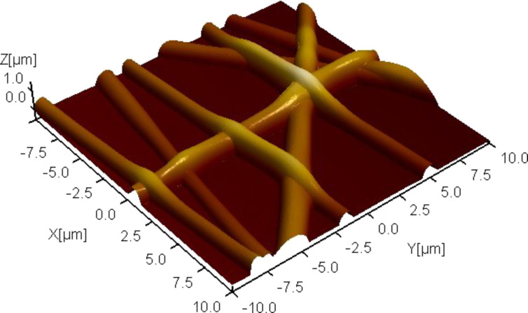
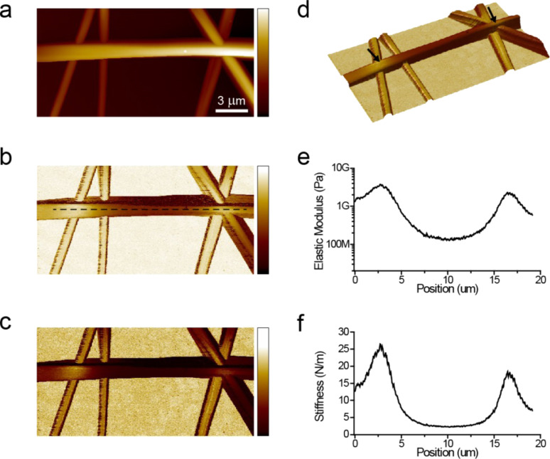
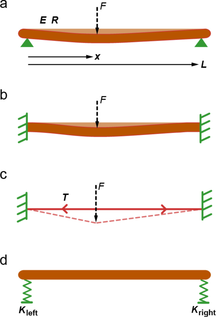
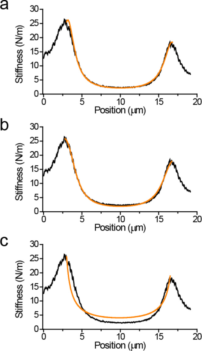
Atomic force microscopes have become indispensable tools for mechanical characterization of nanoscale and submicron structures. However, materials with complex geometries, such as electrospun fiber networks used for tissue scaffolds, still pose challenges due to the influence of tension and bending modulus on the response of the suspended structures. Here we report mechanical measurements on electrospun silk fibers with various treatments that allow discriminating among the different mechanisms that determine the mechanical behavior of these complex structures. In particular we were able to identify the role of tension and boundary conditions (pinned versus clamped) in determining the mechanical response of electrospun silk fibers. Our findings show that high-resolution mechanical imaging with torsional harmonic atomic force microscopy provides a reliable method to investigate the mechanics of materials with complex geometries.
Keywords: atomic force microscopy; nanomechanical characterization; silk fibers; tissue scaffolds; torsional harmonic cantilevers.
Figures
Similar articles
-
Quantitative imaging of electrospun fibers by PeakForce Quantitative NanoMechanics atomic force microscopy using etched scanning probes.Micron. 2015 May;72:1-7. doi: 10.1016/j.micron.2015.01.005. Epub 2015 Feb 9. Micron. 2015. PMID: 25710786
-
Mechanical characterization of electrospun polyesteretherurethane (PEEU) meshes by atomic force microscopy.Clin Hemorheol Microcirc. 2019;73(1):229-236. doi: 10.3233/CH-199201. Clin Hemorheol Microcirc. 2019. PMID: 31561331
-
Mechanical testing of electrospun PCL fibers.Acta Biomater. 2012 Jan;8(1):218-24. doi: 10.1016/j.actbio.2011.08.015. Epub 2011 Aug 22. Acta Biomater. 2012. PMID: 21878398
-
Nanomechanics of Cells and Biomaterials Studied by Atomic Force Microscopy.Adv Healthc Mater. 2015 Nov 18;4(16):2456-74. doi: 10.1002/adhm.201500229. Epub 2015 Jul 22. Adv Healthc Mater. 2015. PMID: 26200464 Review.
-
Measurement of nanomechanical properties of biomolecules using atomic force microscopy.Micron. 2012 Feb;43(2-3):116-28. doi: 10.1016/j.micron.2011.07.017. Epub 2011 Aug 6. Micron. 2012. PMID: 21890365 Review.
Cited by
-
Atomic Force Microscopy: A Powerful Tool to Address Scaffold Design in Tissue Engineering.J Funct Biomater. 2017 Feb 13;8(1):7. doi: 10.3390/jfb8010007. J Funct Biomater. 2017. PMID: 28208801 Free PMC article.
References
-
- Forchheimer D, Platz D, Tholén E A, Haviland D B. Phys Rev B. 2012;85:195449. doi: 10.1103/PhysRevB.85.195449. - DOI
LinkOut - more resources
Full Text Sources
Other Literature Sources