. 2013 Jul;70(1):241-7.
doi: 10.1002/mrm.24766. Epub 2013 Apr 29.

Integrated parallel reception, excitation, and shimming (iPRES)

Affiliations

Integrated parallel reception, excitation, and shimming (iPRES)

Hui Han et al. Magn Reson Med. 2013 Jul.

Abstract

Purpose: To develop a new concept for a hardware platform that enables integrated parallel reception, excitation, and shimming.

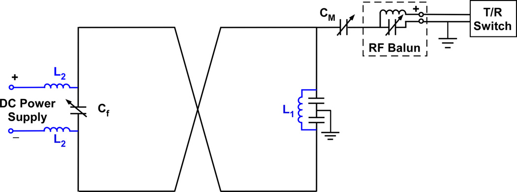
Theory: This concept uses a single coil array rather than separate arrays for parallel excitation/reception and B0 shimming. It relies on a novel design that allows a radiofrequency current (for excitation/reception) and a direct current (for B0 shimming) to coexist independently in the same coil.

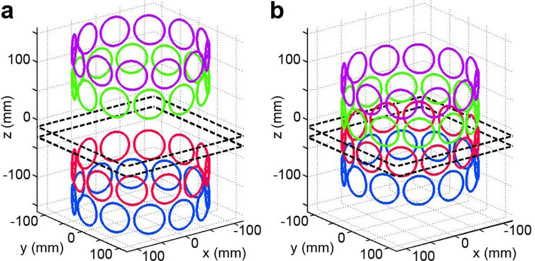
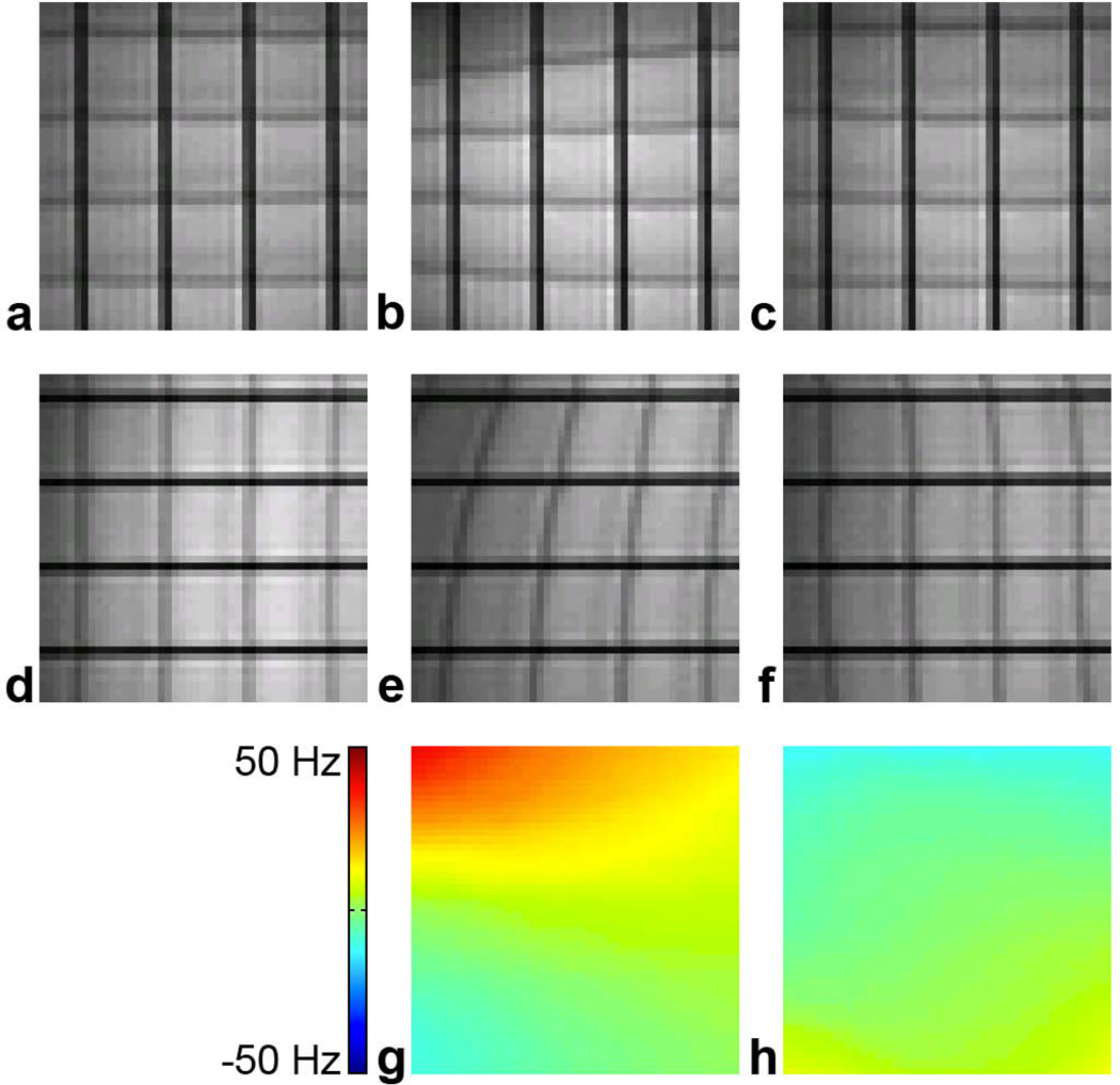
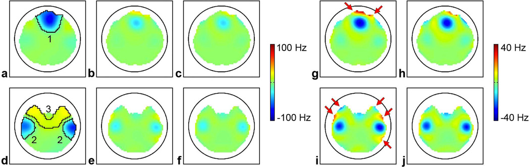
Methods: Proof-of-concept B0 shimming experiments were performed with a two-coil array in a phantom, whereas B0 shimming simulations were performed with a 48-coil array in the human brain.

Results: Our experiments show that individually optimized direct currents applied in each coil can reduce the B0 root-mean-square error by 62-81% and minimize distortions in echo-planar images. The simulations show that dynamic shimming with the 48-coil integrated parallel reception, excitation, and shimming array can reduce the B0 root-mean-square error in the prefrontal and temporal regions by 66-79% as compared with static second-order spherical harmonic shimming and by 12-23% as compared with dynamic shimming with a 48-coil conventional shim array.

Conclusion: Our results demonstrate the feasibility of the integrated parallel reception, excitation, and shimming concept to perform parallel excitation/reception and B0 shimming with a unified coil system as well as its promise for in vivo applications.


Figures

FIG. 1
FIG. 1
Schematic circuit of the modified figure-8 coil. The addition of an inductor L1 in conjunction with a DC power supply forms a closed DC loop and allows a DC current to circulate in the figure-8 pathway. The inductors L2 prevent the propagation of RF currents. The RF balun reduces RF coupling between the coil and the surrounding. Cf and Cm are tuning and matching capacitors, respectively.
FIG. 2
FIG. 2
Conventional shim coil array (a) and iPRES coil array (b) used in the simulations. Each ring of coils is drawn in a different color for clarity. The dashed lines denote the location of the two axial slices shown in Fig. 6.
FIG. 3
FIG. 3
B0 maps acquired with a DC current of 130 mA applied either in the single-loop coil (a) or in the figure-8 coil (b), after subtraction of the baseline B0 map acquired with no DC current.
FIG. 4
FIG. 4
Reduction of linear B0 inhomogeneities. EPI images with frequency direction = right/left (horizontal) (a–c) or superior/inferior (vertical) (d–f) and B0 maps (g–h) acquired with no linear shim offsets and no DC currents (a,d), with linear shim offsets and no DC currents (b,e,g), or with linear shim offsets and optimal DC currents (c,f,h). The baseline B0 map acquired with no linear shim offsets and no DC currents was first subtracted from those acquired with the other two conditions to yield the B0 maps shown in (g,h).
FIG. 5
FIG. 5
Reduction of localized nonlinear B0 inhomogeneities. EPI images with frequency direction = right/left (horizontal) (a–c) or superior/inferior (vertical) (d–f) and B0 maps (g–h) acquired with no coins and no DC currents (a,d), with coins and no DC currents (b,e,g), or with coins and optimal DC currents (c,f,h). The baseline B0 map acquired with no coins and no DC currents was first subtracted from those acquired with the other two conditions to yield the B0 maps shown in (g,h).
FIG. 6
FIG. 6
B0 maps in two axial slices through the prefrontal cortex (a–c) and temporal lobes (d–f) after static 2nd-order SH shimming alone (a,d) or after additional dynamic shimming with the conventional shim coil array (b,e) or the iPRES coil array (c,f). The circle denotes the location of the coil array. The maps shown in (g,h,i,j) are the same as those shown in (b,c,e,f), respectively, but with a different scaling to highlight the differences between the two setups.

References

    1. Blamire AM. The technology of MRI — the next 10 years? Brit J Radiol. 2008;81:601–617. - PubMed
    1. Bernstein MA, Huston J, Ward HA. Imaging artifacts at 3.0T. J Magn Reson Imaging. 2006;24:735–746. - PubMed
    1. Vaughan T, DelaBarre L, Snyder C, Tian JF, Akgun C, Shrivastava D, et al. 9.4T human MRI: preliminary results. Magn Reson Med. 2006;56:1274–1282. - PMC - PubMed
    1. Setsompop K, Wald LL, Alagappan V, Gagoski B, Hebrank F, Fontius U, Schmitt F, Adalsteinsson E. Parallel RF transmission with eight channels at 3 Tesla. Magn Reson Med. 2006;56:1163–1171. - PubMed
    1. Koch KM, Rothman DL, de Graaf RA. Optimization of static magnetic field homogeneity in the human and animal brain in vivo. Prog Nucl Magn Reson Spectrosc. 2009;54:69–96. - PMC - PubMed

Publication types