. 2013 May 14;110(20):8093-8.
doi: 10.1073/pnas.1221677110. Epub 2013 Apr 29.

Quantification of cellular penetrative forces using lab-on-a-chip technology and finite element modeling

Affiliations

Quantification of cellular penetrative forces using lab-on-a-chip technology and finite element modeling

Amir Sanati Nezhad et al. Proc Natl Acad Sci U S A. .

Abstract

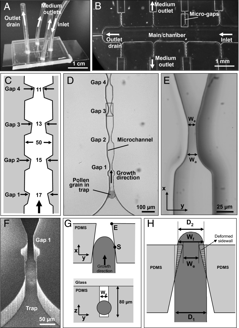
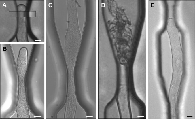
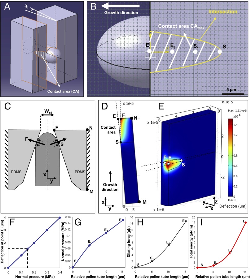
Tip-growing cells have the unique property of invading living tissues and abiotic growth matrices. To do so, they exert significant penetrative forces. In plant and fungal cells, these forces are generated by the hydrostatic turgor pressure. Using the TipChip, a microfluidic lab-on-a-chip device developed for tip-growing cells, we tested the ability to exert penetrative forces generated in pollen tubes, the fastest-growing plant cells. The tubes were guided to grow through microscopic gaps made of elastic polydimethylsiloxane material. Based on the deformation of the gaps, the force exerted by the elongating tubes to permit passage was determined using finite element methods. The data revealed that increasing mechanical impedance was met by the pollen tubes through modulation of the cell wall compliance and, thus, a change in the force acting on the obstacle. Tubes that successfully passed a narrow gap frequently burst, raising questions about the sperm discharge mechanism in the flowering plants.

Keywords: cell mechanics; invasive growth; microfluidics; sexual plant reproduction; tip growth.


Conflict of interest statement

The authors declare no conflict of interest.

Figures

Fig. 1.
Fig. 1.
Experimental setup for the exposure of pollen tubes to microgaps and geometry of interaction. (A) Macro photograph of the TipChip illustrating arrangements of inlet and outlets. (B) Micrograph showing the geometry of the microfluidic network. (C) Dimensions of the microchannel with repeated narrow regions (microgaps). Numbers are in micrometers; the drawing does not reflect the aspect ratio. (D) Bright field micrograph of the geometry of a microchannel comprising the channel entrance with a trapped pollen grain and four subsequent gaps. (E) Close-up micrograph of a microgap indicated in D, showing an opening with Wa and We. (F) Scanning electron micrograph of the entrance of a microchannel and the first microgap viewed from an oblique angle. (G) Simplified schematic views of the interaction between an elongating pollen tube (dark gray) and a microgap. The pollen tube initially is in contact with both tapered sidewalls forming the microgap at point S. The microgap is formed as a rectangular, slit-shaped opening (white) in the PDMS material (light gray). (H) The passing pollen tube deforms the PDMS sidewalls of the gap to change the gap width at the narrowest section from We to Wf. During passage through the gap, the original width of the pollen tube D1 temporarily is reduced to D2 but typically widens after passing the gap.
Fig. 2.
Fig. 2.
Different types of pollen tube behavior during passage through a microgap. (A) The pollen tube deflects the sidewalls almost completely to maintain its diameter. (Inset) Same position of the undeformed microgap before the invasion of the pollen tube. (B) The pollen tube becomes narrower in the y-direction to pass the gap and widens to the original diameter after passage. (C) The pollen tube becomes wider than the original tube after passing the gap, but eventually returns to the original diameter. (D) Following passage through the gap, the pollen tube bursts. (E) The pollen tube stalls and cannot pass through the gap. The buckling indicates that a force is exerted against the wall of the gap. Bars: 10 µm (bar in A applies to AD).
Fig. 3.
Fig. 3.
Behavior of pollen tubes during passage through a microgap. (A) Effect of the ratio between pollen tube diameter and gap width on pollen tube behavior. Between ratios of 1.00 and 1.20, the pollen tubes deform the gap to pass almost without narrowing their diameter (green ▲). Below this ratio, the pollen tube diameter is reduced (light blue ◇) and frequently the tubes burst upon returning to the original diameter following gap passage (solid blue ◆). At a ratio of 1.33 and below, the tubes stall and cannot pass the gap (red ■). Each data point represents one interaction between a pollen tube and a microgap. (B) Change in growth rate during microgap passage. Upon encountering the gap at point S, the tube slows considerably but shows a constant growth rate despite the continuously narrowing gap. After exiting the narrowest region at point E, it starts growing faster but bursts soon after.
Fig. 4.
Fig. 4.
Finite element model for the simulation of force exertion by the pollen tube on the sidewalls of the microgap. (A) Three-dimensional representation indicating the contact surface between the pollen tube and microgap when the pollen tube is in maximum contact with the sidewall. (B) Position of four reference points on the contact area, starting with point S upon initial contact and ending with point E, the exit of the gap. Points S1 and E1 are two sample points equally spaced between S and E. (C) Top view of the simulated geometry, indicating the orientation of the force vectors. (D and E) Top view (D) and 3D view (E) of sidewall deflection at effective pressure P = 0.15 MPa. The color code represents the deflection of the PDMS material. (F) Effect of varying effective pressure on sidewall deflection at point E as simulated by the finite element model. (G) Normal pressure required for sidewall deformation during pollen tube passage through the gap. (H) Dilating force F required for sidewall deformation during pollen tube passage through the gap. (I) Total energy required for sidewall deflection during pollen tube passage through the gap. (GI) The values are plotted as a function of the pollen tube length, measured relative to the initial length of the tube at the moment of first contact with the microgap wall.

References

    1. Ishijima A, Doi T, Sakurada K, Yanagida T. Sub-piconewton force fluctuations of actomyosin in vitro. Nature. 1991;352(6333):301–306. - PubMed
    1. Theriot JA. The polymerization motor. Traffic. 2000;1(1):19–28. - PubMed
    1. Cojoc D, et al. Properties of the force exerted by filopodia and lamellipodia and the involvement of cytoskeletal components. PLoS One. 2007;2(10):e1072. - PMC - PubMed
    1. Schopfer P. Biomechanics of plant growth. Am J Bot. 2006;93(10):1415–1425. - PubMed
    1. Lew RR. Mass flow and pressure-driven hyphal extension in Neurospora crassa. Microbiology. 2005;151(Pt 8):2685–2692. - PubMed

Publication types