Comparative Study
. 2013 Jul;8(4):481-509.
doi: 10.1007/s11548-013-0825-7. Epub 2013 Apr 30.

Three-dimensional histological specimen preparation for accurate imaging and spatial reconstruction of the middle and inner ear

Affiliations
Comparative Study

Three-dimensional histological specimen preparation for accurate imaging and spatial reconstruction of the middle and inner ear

Thomas S Rau et al. Int J Comput Assist Radiol Surg. 2013 Jul.

Abstract

Purpose: This paper presents a highly accurate cross-sectional preparation technique. The research aim was to develop an adequate imaging modality for both soft and bony tissue structures featuring high contrast and high resolution. Therefore, the advancement of an already existing micro-grinding procedure was pursued. The central objectives were to preserve spatial relations and to ensure the accurate three-dimensional reconstruction of histological sections.

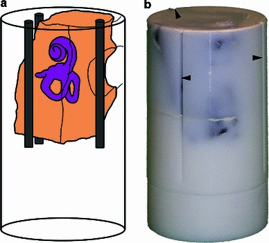
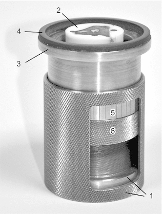
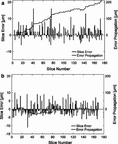
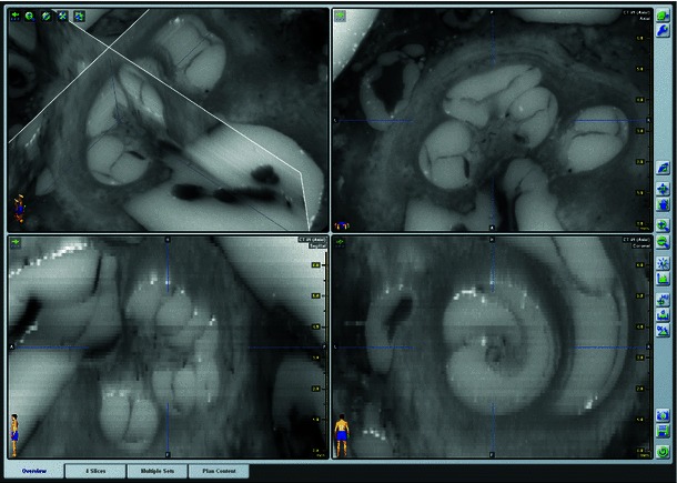
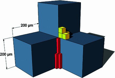
Methods: Twelve human temporal bone specimens including middle and inner ear structures were utilized. They were embedded in epoxy resin, then dissected by serial grinding and finally digitalized. The actual abrasion of each grinding slice was measured using a tactile length gauge with an accuracy of one micrometre. The cross-sectional images were aligned with the aid of artificial markers and by applying a feature-based, custom-made auto-registration algorithm. To determine the accuracy of the overall reconstruction procedure, a well-known reference object was used for comparison. To ensure the compatibility of the histological data with conventional clinical image data, the image stacks were finally converted into the DICOM standard.

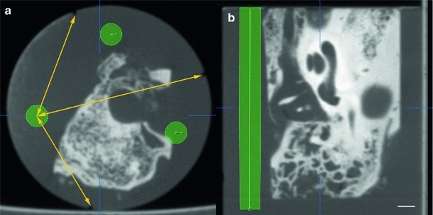
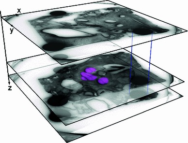
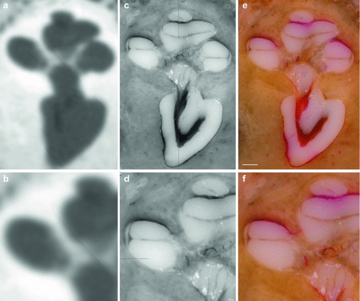
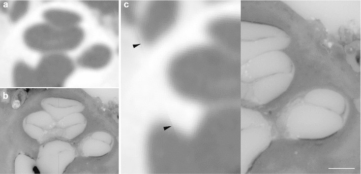
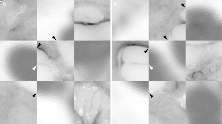
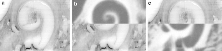
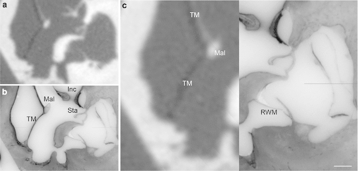
Results: The image fusion of data from temporal bone specimens' and from non-destructive flat-panel-based volume computed tomography confirmed the spatial accuracy achieved by the procedure, as did the evaluation using the reference object.

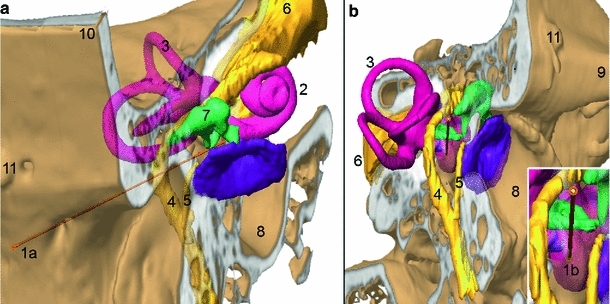
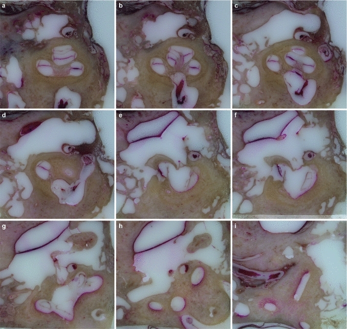
Conclusion: This systematic and easy-to-follow preparation technique enables the three-dimensional (3D) histological reconstruction of complex soft and bony tissue structures. It facilitates the creation of detailed and spatially correct 3D anatomical models. Such models are of great benefit for image-based segmentation and planning in the field of computer-assisted surgery as well as in finite element analysis. In the context of human inner ear surgery, three-dimensional histology will improve the experimental evaluation and determination of intra-cochlear trauma after the insertion of an electrode array of a cochlear implant system.


Conflict of interest statement

The authors declare that they have no conflict of interest.

Figures

Fig. 1
Fig. 1
Preoperative planning founded on flat-panel-based volume computed tomography (fpVCT) imaging. a Slightly superior frontal view of the lateral skull base. b Lateral view, slightly posterior and inferior, showing a planned trajectory (1a1b) for minimally invasive access to the inner ear (2, cochlea). a, b CT-based imaging allows the identification of the functional structures of the lateral skull base: cochlea (2), vestibular system (3), facial nerve (4), chorda tympani (5), vestibulocochlear nerve (6) and ossicular chain (7). Additionally, the external ear canal (8) with tympanic membrane, the zygomatic process of the temporal bone (9), squama temporalis (3) and artefacts of a bone-anchored screw (11) serving as fiducial markers for the registration procedure are visible. Apart from the ossicles, all structures are segmented indirectly using the high contrast of their bony walls. Using these patient-specific anatomical data, a trajectory serving as a minimally invasive access to the inner ear can be planned, starting at the surface of the temporal bone (1a) and entering the cochlea near the round window membrane (1b). However, intra-cochlear structures such as the basilar membrane which are essential to planning the insertion of a cochlear implant electrode are not visible
Fig. 2
Fig. 2
Intra-cochlear anatomical structures. a Histological microgrinding preparation of the human inner ear after embedding in epoxy resin (dyed with titanium dioxide, formula image) and acid violet staining of the soft tissues. b Close-up of the basal turn. An electrode array of a cochlear implant system needs to be inserted into the scala tympani (ST) without harming the basilar membrane (BM) or other internal structures. TB surrounding temporal bone, NC nervus cochlearis, SV scala vestibule, SM scala media, RM Reissner’s membrane, OSL Osseous spiral lamina. (TB1R, scale bar is 1 mm)
Fig. 3
Fig. 3
Embedding of the temporal bone specimen. a Schematic drawing of the embedded temporal bone specimen showing its location within the cylindrical sample of epoxy resin as well as three artificial registration markers. b The photograph of the hardened sample shows the three longitudinal grooves (black markers) milled on the surface for accuracy measurement
Fig. 4
Fig. 4
Planning of the registration markers. Trajectory planning allows the definition of proper locations for the three artificial registration markers avoiding damage of essential structures of the specimen (a: axial view, b: sagittal view). Triangulation (symbolized by the yellow arrows), using the milled grooves on the surface as reference points, allows the transfer of the planned locations for the registration markers to the base area of the sample. The scale bar is 2 mm
Fig. 5
Fig. 5
Custom-made specimen holder for controlled manual grinding. The special grinding tool consists of two main parts. The inner part (1) secures the embedded specimen (2). The outer part (3) is equipped with an abrasion-resistant hard ceramic ring (4) which defines the grinding surface. An added scale (5) allows easy adjustment of a specific amount of abrasion and a look ring (6) ensures preservation of the setting during the grinding process
Fig. 6
Fig. 6
Three-dimensional reconstruction of the cross-sectional images as part of the conversion into the Dicom data set. The artificial registration markers enable accurate image alignment (as indicated by blue lines). The measured abrasion distance provides the necessary information to locate each slice in the spatial image stack for an accurate 3D reconstruction of the specimen. Abrasion distances were added cummulatively. For ease of identification, the cochlea is highlighted in magenta in this schematic drawing
Fig. 7
Fig. 7
Error propagation of the microgrinding procedure. The difference between the theoretical location of each grinding surface (if equidistant abrasion of 100 formula image is assumed) and the actually measured abrasion was investigated. The bar plot shows the deviation from 100 formula image abrasion for each grinding surface (slice error). The total error (line plot) is a theoretical value determined by the idealized location of the slice as a multiple of 100 formula image and the actual location by the accumulated measured abrasion distances (error propagation). During the study, two different kinds of error propagation were observed: a in principle an excessive amount of abrasion (type 1, e.g., TB-4R), and b completely non-predictable progress of error propagation with partial compensation (type 2, e.g., TB-1R). A tendency towards insufficient amount of abrasion was not observed during the study
Fig. 8
Fig. 8
Successive series of cross-sectional images through the human inner and middle ear showing soft and bony tissue structures (TB-6L)
Fig. 9
Fig. 9
Three-dimensional Dicom data set of the histological microgrinding images. Screenshot of a Dicom data set loaded into the commercial clinical planning software iPlan ENT 2.6 (BrainLAB AG Feldkirchen, Germany) demonstrating the true three-dimensional character of the reconstructed histological cross-sectional images (3D histology). The subfigure on the top right shows the original histological image, whereas the subfigures in the lower panel correspond to reconstructed views (“sagittal” and “coronal” orientation). Even oblique reconstruction is possible (not shown)
Fig. 10
Fig. 10
Corresponding views of the inner ear. a, b fpVCT, c, d 3D histological cross-sectional imaging after converting into the Dicom standard and e, f the original histological image. Radiology-based imaging provides only information about the bony boundary of the cochlea (a, b) and a blurred visualization in regions with thin bony structures containing a meshwork of vessels and neuronal tissue such as the modiolus with the cochlear nerve. In comparison, the presented procedure enables the visualization of both soft tissue structures such as the basilar membrane and stria vascularis, and thin bony structures like the osseous spiral lamina. Solely, neuronal structures cannot be completely preserved as the dehydration step, which causes their shrinking (c, e), is a necessary part of specimen preparation. The lower panel shows close-ups of the images (a), (c) and (e). (TB-1R, scale bar is 1 mm)
Fig. 11
Fig. 11
Image fusion of radiological and histological imaging. Image fusion of fpVCT data (a) and the 3D histology (b) of the same specimen for the comparative visualization of cochlear structures. While soft tissue structures such as the basilar membrane and stria vascularis—and also the osseous spiral lamina—are not visible in the radiological imaging method, these structures can be easily identified in the corresponding histological cross-sectional image. The artefact in the subimage (c, black arrows) is caused by the multiplanar reformation during image fusion which was performed in such a way that the histological image data remained unchanged, whereas the fpVCT data with isotropic voxels were transformed. (TB-1L, scale bar is 1 mm)
Fig. 12
Fig. 12
Image fusion to determine the reconstruction quality. Image fusion of a three-dimensional histological data set with the fpVCT data of the same specimen (see Fig. 10 for a total view of the microgrinding slice and the correlated layer in the fpVCT data). Due to the high degree of conformity between the shape of bony boundaries in both imaging methods (black arrows), it appears reasonable to assume that the locations of soft tissue structures such as the basilar membrane (attached to the lamina spiralis ossea, white arrows) can also be transferred with high accuracy. (TB-1R)
Fig. 13
Fig. 13
Orthogonal plane reconstruction due to true three-dimensional character of the micogrinding procedure. (a) Sagittal view of the same specimen as in Figs. 10 and 12. The abrasion distance is visible as slight bands. (b-c) Comparison with the corresponding fpVCT data after image fusion also shows the high accuracy. (TB-1R)
Fig. 14
Fig. 14
Histological imaging of the middle ear. Image fusion of fpVCT data (a) and the 3D histology (b) of the same specimen for the comparative visualization (c) of middle and inner ear structures around the round window. Conformity of bony boundaries in both imaging methods underlines the quality of the three-dimensional histological sample preparation procedure. TM tympanic membrane, Mal Malleus, Inc, Incus, Sta Stapes with footplate, RWM round window membrane. (TB-5L, scale bar is 1 mm)
Fig. 15
Fig. 15
Comparison of the voxel size of different image modalities. The grey blue voxels represent the physical resolution of the used flat-panel volume computed tomography with an isotropic edge length of 200 formula image. The yellow cubes symbolize the resolution of a micro-CT scanner used in former studies with a voxel size of approximately 30 formula image. Finally, the red cuboidal volumes represent the voxel size of the presented microgrinding procedure with a length of 100 formula image in the direction of abrasion and approximately 16 formula image in the grinding plane

Similar articles

Cited by

References

    1. Adunka O, Gstoettner W, Hambek M, Unkelbach MH, Radeloff A, Kiefer J. Preservation of basal inner ear structures in cochlear implantation. ORL J Otorhinolaryngol Relat Spec. 2004;66(6):306–312. doi: 10.1159/000081887. - DOI - PubMed
    1. Aerts J, Dirckx J, Dierick M, Van Hoorebeke L (2012) High-resolution 3D surface model of bone and soft tissue structures in the human middle ear. Assoc Res Otolaryngol Abstr 134, p 47
    1. Aschendorff A, Kubalek R, Hochmuth A, Bink A, Kurtz C, Lohnstein P, Klenzner T, Laszig R. Imaging procedures in cochlear implant patients—evaluation of different radiological techniques. Acta Otolaryngol. 2004;124(S552):46–49. doi: 10.1080/03655230410017175. - DOI - PubMed
    1. Aschendorff A, Kubalek R, Turowski B, Zanella F, Hochmuth A, Schumacher M, Klenzner T, Laszig R. Quality control after cochlear implant surgery by means of rotational tomography. Otol Neurotol. 2005;26(1):34–37. doi: 10.1097/00129492-200501000-00007. - DOI - PubMed
    1. Balachandran R, Mitchell JE, Blachon G, Noble JH, Dawant BM, Fitzpatrick JM, Labadie RF. Percutaneous cochlear implant drilling via customized frames: an in vitro study. Otolaryngol Head Neck Surg. 2010;142(3):421–426. doi: 10.1016/j.otohns.2009.11.029. - DOI - PMC - PubMed

Publication types

MeSH terms