

Delivery of S1P receptor-targeted drugs via biodegradable polymer scaffolds enhances bone regeneration in a critical size cranial defect
- PMID: 23640833
- PMCID: PMC3951302
- DOI: 10.1002/jbm.a.34779
Delivery of S1P receptor-targeted drugs via biodegradable polymer scaffolds enhances bone regeneration in a critical size cranial defect
Abstract
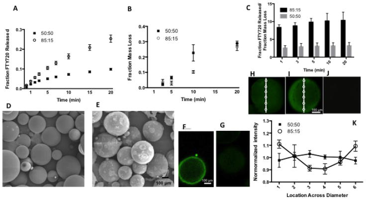
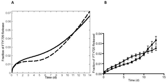
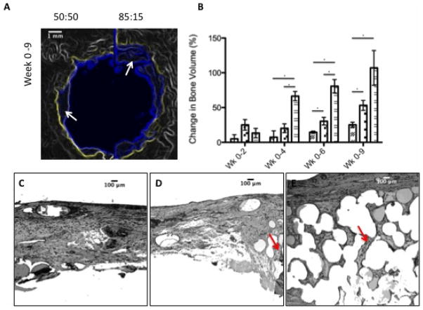
Biodegradable polymer scaffolds can be used to deliver soluble factors to enhance osseous remodeling in bone defects. To this end, we designed a poly(lactic-co-glycolic acid) (PLAGA) microsphere scaffold to sustain the release of FTY720, a selective agonist for sphingosine 1-phosphate (S1P) receptors. The microsphere scaffolds were created from fast degrading 50:50 PLAGA and/or from slow-degrading 85:15 PLAGA. Temporal and spatial regulation of bone remodeling depended on the use of appropriate scaffolds for drug delivery. The release profiles from the scaffolds were used to design an optimal delivery system to treat critical size cranial defects in a rodent model. The ability of local FTY720 delivery to maximize bone regeneration was evaluated with micro-computed tomography (microCT) and histology. Following 4 weeks of defect healing, FTY720 delivery from 85:15 PLAGA scaffolds resulted in a significant increase in bone volumes in the defect region compared to the controls. A 85:15 microsphere scaffolds maintain their structural integrity over a longer period of time, and cause an initial burst release of FTY720 due to surface localization of the drug. This encourages cellular in-growth and an increase in new bone formation.
Keywords: biodegradable polymer scaffolds; bone tissue engineering; drug delivery.
Copyright © 2013 Wiley Periodicals, Inc.
Figures
 ), the 50:50 side of the 50:50–85:15 scaffold (
 ), and the 85:15 side of the 50:50–85:15 scaffold (
 ). *Statistical significance, where p<0.05. This result is reflected in the histology. (C) Untreated empty defects have minimal bone formation. (D) The side treated with 50:50 microsphere scaffold swells and loses pore volume and has less bone formation (red arrows) compared to the side treated with (E) 85:15 microsphere scaffold. All histological analysis was done 9 weeks after treatment.
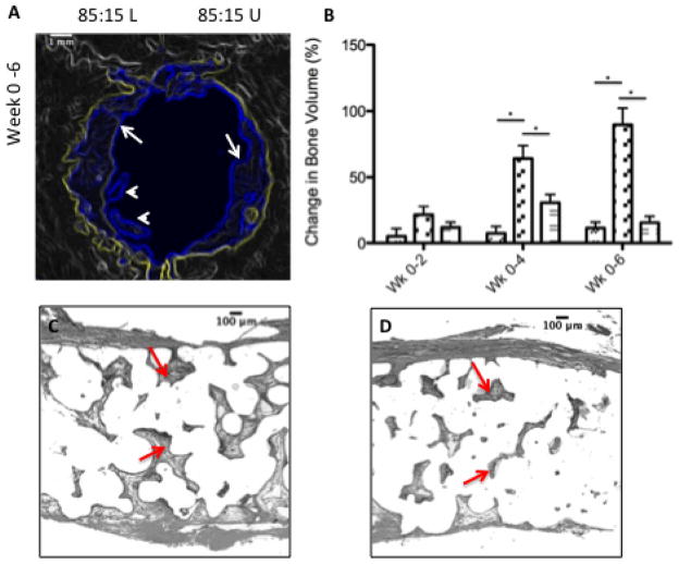 ), the FTY720-loaded side of the 85:15 (L)(
) scaffold, and the unloaded side of the 85:15 (U) scaffold (
). *Statistical significance, where p<0.05. This result is reflected in the histology. (C) The loaded side of the scaffold (left) shows more bone formation (red arrows) compared to the (D) unloaded side (right). All histological analysis was done 6 weeks after treatment.
), the FTY720-loaded side of the 85:15 (L)(
) scaffold, and the unloaded side of the 85:15 (U) scaffold (
). *Statistical significance, where p<0.05. This result is reflected in the histology. (C) The loaded side of the scaffold (left) shows more bone formation (red arrows) compared to the (D) unloaded side (right). All histological analysis was done 6 weeks after treatment.Similar articles
-
Local delivery of FTY720 accelerates cranial allograft incorporation and bone formation.Cell Tissue Res. 2012 Mar;347(3):553-66. doi: 10.1007/s00441-011-1217-3. Epub 2011 Aug 24. Cell Tissue Res. 2012. PMID: 21863314 Free PMC article.
-
Delivery of bioactive lipids from composite microgel-microsphere injectable scaffolds enhances stem cell recruitment and skeletal repair.PLoS One. 2014 Jul 31;9(7):e101276. doi: 10.1371/journal.pone.0101276. eCollection 2014. PLoS One. 2014. PMID: 25077607 Free PMC article.
-
FTY720 promotes local microvascular network formation and regeneration of cranial bone defects.Tissue Eng Part A. 2010 Jun;16(6):1801-9. doi: 10.1089/ten.TEA.2009.0539. Tissue Eng Part A. 2010. PMID: 20038198 Free PMC article.
-
Production and release of sphingosine 1-phosphate and the phosphorylated form of the immunomodulator FTY720.Biochim Biophys Acta. 2008 Sep;1781(9):496-502. doi: 10.1016/j.bbalip.2008.05.003. Epub 2008 Jun 13. Biochim Biophys Acta. 2008. PMID: 18555808 Review.
-
Using scaffolds as drug delivery systems to treat bone tumor.Nanotechnology. 2022 Mar 4;33(21). doi: 10.1088/1361-6528/ac5017. Nanotechnology. 2022. PMID: 35092950 Review.
Cited by
-
FTY720 in immuno-regenerative and wound healing technologies for muscle, epithelial and bone regeneration.Front Physiol. 2023 May 12;14:1148932. doi: 10.3389/fphys.2023.1148932. eCollection 2023. Front Physiol. 2023. PMID: 37250137 Free PMC article. Review.
-
Osteoimmunology: Interactions With the Immune System in Spinal Fusion.Int J Spine Surg. 2023 Dec 27;17(S3):S9-S17. doi: 10.14444/8556. Int J Spine Surg. 2023. PMID: 38050073 Free PMC article.
-
Adjuvant Drug-Assisted Bone Healing: Advances and Challenges in Drug Delivery Approaches.Pharmaceutics. 2020 May 6;12(5):428. doi: 10.3390/pharmaceutics12050428. Pharmaceutics. 2020. PMID: 32384753 Free PMC article. Review.
-
Amphiphilic degradable polymers for immobilization and sustained delivery of sphingosine 1-phosphate.Acta Biomater. 2014 Jul;10(7):3079-90. doi: 10.1016/j.actbio.2014.02.051. Epub 2014 Mar 12. Acta Biomater. 2014. PMID: 24631657 Free PMC article.
-
Nanofiber-Based Delivery of Bioactive Lipids Promotes Pro-regenerative Inflammation and Enhances Muscle Fiber Growth After Volumetric Muscle Loss.Front Bioeng Biotechnol. 2021 Mar 19;9:650289. doi: 10.3389/fbioe.2021.650289. eCollection 2021. Front Bioeng Biotechnol. 2021. PMID: 33816455 Free PMC article.
References
-
- Woo EJ. Recombinant human bone morphogenetic protein-2: adverse events reported to the Manufacturer and User Facility Device Experience database. Spine J. 2012 Oct;12(10):894–9. - PubMed
-
- Chen RR, Silva EA, Yuen WW, Brock AA, Fischbach C, Lin AS, Guldberg RE, Mooney DJ. The FASEB journal : official publication of the Federation of American Societies for Experimental Biology. 2007;21:3896–903. - PubMed
Publication types
MeSH terms
Substances
Grants and funding
LinkOut - more resources
Full Text Sources
Other Literature Sources
